|

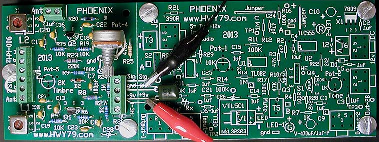
C18, C20 & C27
= .1uf A different
style from photo are should be used so I can tell them apart if you took a photo
of your board.
With the two 3 x 3 oscillator section boards
stuffed you want to determine which board has the sweeter waveform. This
board will be used for the Pitch generation along with using the Lev Antenna.
Place leads at the HE-1 terminal in the +9v
& gnd. This could be a >= 10k resistor or a non-electrolytic capacitor
just to use its leads.
Place a jumper wire
across C & D at the ABCD terminal. This grounds the L1 shield for a
warmer sound.
Testing can be done with Pot-4 installed, if
installed set it to halfway. The jumper wire seen under Pot-4 allows
a board mounted Pot to adjust in either direction for personal preference.
You could mount a terminal
here for a remote Pot-4 using a twisted wire pair. If a terminal is
mounted place a 470 ohm resistor across it for temporary circuit testing.
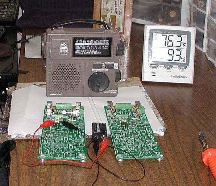
Place your two PCB's if you stuffed two boards
with an AM Radio on a piece of ~12" x 12" aluminum foil with typing
paper over it for insulation. Alligator clip the foil to the negative side
of the 9 volt battery. This test helps give you understand in how the RF
tuning for the Null point is done once you have your setup complete using
the Lev Antenna.
See the setup photo at the bottom of this page
Use alligator clips to attach a 9v battery
to the pcb, getting the polarity backward will not hurt anything just
switch the connection so it works. Use another alligator lead and connect
the foil to the negative battery side.
| No earth
ground or antenna is used or connected for this experiment.
Test: Power the boards one
at a time to make sure they work. On the board connected to power adjust the IFT coil L2
until you hear a quieting spot show up over your AM
Radio which is tuned to around 870 kHz.
Now adjust IFT coil L1 to
this same spot and the heterodyne whistle will show up. The
Null Point is where the Pitch whistle goes quiet then the
tone rises again on the opposite side of the quiet spot.
This is the most
"exciting" moment in theremin building . . . Heterodyning!!!
Move your finger near the top of Q1
and it should push the Pitch whistle lower, if the pitch rises you’re
on the wrong side of the Null Point. Readjust L1 to the
other side of the quiet spot which is also known as the Null
Point. The Pitch whistle will rise on either side of the Null
Point when tuning L1. Adjust to the side that gives you the
proper response direction which is the Pitch rising as you
approach the antenna.
If one of the oscillators
does not have a quiet spot
over the AM Radio and heterodyning does not occur while tuning re-check the part values and soldering on that
oscillator.
|
Do this process on both PCB's.
Volume Control needs a spikier or rougher
waveform. Peek at the Volume
Control webpage.
The time has come to complete the board stuffing
of the 5.2 x 3 section parts. The theremin tone will blast out the Out-2B
jack into your amplifier once the IC's are installed. The same quick
test above could be repeated once the full board is stuffed without the
antennas or earth ground connected. The Output whistle is then taken from Out-2B, no
radio. The radio is a great troubleshooting tool in the future to hear if
the oscillators are working. If tapping the top of one of the transistors
causes a whistle over the radio then it is that sides IF coil that needs
to be turned clockwise slightly.
<=Back
to Basic Pitch Setup

.
|