|
This is the 2013 Commercial
Circuit Board

It looks
nicer to mount the longer wires on the bottom side of the pc board.
| The pitch board gets
power through J2 and a cable from the volume control board. The 3
x 3 section is powered by 9 volts while the 7809 on the 3 x 5
pitch section is replaced by a 7805 for 5 volts. This needs
clarity in how I wire it.
10.13.18
- On the PC board used for Pitch you must break the connection at
the transformer pad to the ground track under the R of the text
SR3. This is the large square graphic at the bottom of the board.
A jumper wire is soldered to the freed transformer pad to the
emitter of Q3. This connection can be seen on the Clara
Voice PDF Schematic. The 5.2" x 3" Phoenix section
is nearly identical to my Clara Voice 3" x 3" board.
Update
6.11.17
Before any parts are added
you may want to drill a dimple between the 2 & 5 pins of the TRS jacks
so they sit level. Stuff a jack to see what I mean, they will be
at a slight downward angle.
Drill a .031" hole at LED-1 upper pad so a "possible" R32 2.2k can be mounted in the future.
The Phoenix boards are single sided so it is safe to re-drill
holes. Never do this on a multi-layered board.
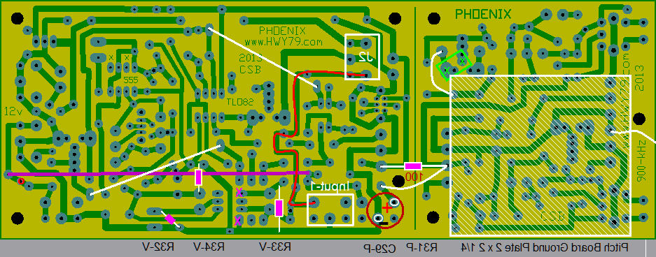
The
purple wire
seen in the graphic
is not needed unless you want to pass the controlled audio signal to the
Out-2B jack on the right side, read down below.
Power
& audio
signal to the Volume
Control
board is passed through the J2
TRS jack
from the pitch board. It could be setup to go from the volume side
to the pitch side.
2N3904 NPN transistors were place back on the
Mouser list so it is complete.
When using these for the oscillators, a 1K pot is used for tuning at the Pot-4 connections.
You may need to add the R25-470R resistor to dampen the tuning response.
MPS-A42 NPN transistors are preferred for the oscillators on the 3 x 3 section.
When using these, a 2K pot is used for tuning at the Pot-4 connections, no R25.
This change in pot
value is the first indicator of a transistor junction that might
have better resistance to thermal drift . The capacitance at the
PN junction is affected by changes in voltage or heat . This is
why some theremin's use this effect for tuning the oscillators.
At Pot-4
you might want to mount a terminal which will fit at an angle. Then it is easier to change different wire lengths
for the pots.
The left side ground
plate mounted
under the 3 x 3 section of the pitch side board is not needed
unless a smoother wave form is desired.
The four added
resistors:
R31-100R
& C29-470uf
are only used on the pitch
side board.
Adding them allows almost any type of wall-wart to be used as
these parts eliminate noise in the most sensitive section of the
theremin.
R32-2K2
(2.2k),
creates more fade range
while quieting the volume
side board. Do not add
at first. R33-
4K7 (4.7k) was added to
quiet the hiss you hear in some of my sound bytes right when the sound
quiets. Mount the resistor on the bottom side of board, the X
shows the two pads
that can be solder to
on the bottom side of
the board. R34-10K
leaks off the charge on C9,
otherwise it could latch up the 555
when power is first applied which will cause the 555 to overheat.
solder on the bottom
side
In proper circuit design the hFE characteristic of a transistor is not in play. I still like to use two transistors in the theremin oscillator section that have matching hFE.
hFE of a transistor is the current gain or amplification factor of a transistor. hFE (which is also referred to as β) is the factor by which the base current is amplified to produce the amplified current of the transistor
Pitch
RF Mixing
RF signal mixing is done by taking a signal off both ungrounded
IF transformer cans at the
ABCD terminals and passing them through the
mixing diode D2 on the 3 x 3 section.
Pot-5 100k has some control over forward biasing
D2 and
RF wave shaping. Adjust Pot
5 for the sweet
spot by listening to the audio output. R23-220k
should "not"
be installed.
My Harmonic Exciter breakout board for capturing Clara’s harmonically rich sound was developed from using
this Phoenix 3” x 5.2” section, they are
theoretically identical. Driving the audio transformer does the
trick of enhancing the sound with even harmonics.
Exciter Schematic
3 x 3 Clara Board
|
Update
3.10.14
C9-470uf
might be changed to 1000uf
on the Volume
Control board.
This prevents the PWM control pulse from being heard in the controlled Pitch. C9
on the Pitch Board
is .1uf this
filters the noise from the 555
output. C29
Mod on the Pitch
Board is changed to
1000uf
to keep the parts list simple. C10
on both boards
are changed to 1000uf
to keep the parts list simple. List is updated. |
The two
thicker white wires
are used only on the Pitch
Board as wire connections to the Harmonic Enhancement
section. The support components are also needed on the Pitch
board. These
are R1-1K, R26-2.2K, R29-
2.2K, C25-1uf and U3.
V1-Transformer with P facing towards Pot-1, this is the same area the
Vactrol V1 mounts on the
Volume Control Board. One of these power
supply is used with the dragonfly
tube/valve theremin to power the
pitch and volume board and would be better for the Phoenix and not
use the 7809
and the C10
capacitors on both Volume and Pitch board. The 7809's would need a jumper
from pin 1 to 3.
The purple
line transfers the Volume Board
sound from Output-1
over to the Out-2B
Jack. Use a drill to open or break the copper trace connection at the
red dot.
Only do this on the Volume Control
board if you choose not to use the Output-1 jack location.
C6 near Input-1 must be installed or there will be no sound out. Rx
& C12 are not installed. The purple wire is not used or needed on the
Pitch Board. The purple wire could be run to a S1 setup so you could
toggle between the controlled audio volume signal or the volume boards own
spiky volume signal for monitoring. Using
the purple
wire allows you to avoid using the three bottom TRS jacks and
taking the signal off one end which includes J2 who's cable feeds
out that side.
The big
white square is the minimum ground plate
which is a piece of raw copper clad pcb cut to 2" x 2" and
mounted with the copper "away from" the soldered connections. It
is electrically connected with a soldered on wire to ground at C on
T1. For increased wave
shaping response you could connect it to D on T1 so Pot-5
controls its influence. A longer ground plate could extend over to
the U1 OP amp to shield against noise.
Mount this
ground plate
after the pcb stand-offs have
been glued into place to get the proper position. Hold the copper clad in place with
a dab of contact cement with the copper clad side to the wood
enclosure. You do not want it under
the L2 side as this will affect the inside linearity of the pitch field.
You want it completely under the L1
IFT coil. Pot-5
fully clockwise brings L1 and the ground plate to ground for the smoothest
wave shape. The
green square is Pot-4 substituted by a terminal. This is the Null Tuning pot which you may want in another location. A
twisted pair of wires will work from here at "any" length. 1 to
10 feet
for remote tuning? LED-1
is paralleled by the R32-2.2k
resistor. This creates the best quiet side volume shading response of any
theremin. Fold over, like an "L" LED-1
(leads = .4" + .5"),
it can slip through the wood box LED hole while soldered to the board. With
R32
in place the volume shading is more gradual through the quiet range.
Without it the volume is a bit quicker. LED-1
is normally < 2.4v. A bit higher than this the volume becomes snappier
for staccato. You could add a switch
so R32 could be flipped in or out of the circuit for the response you desire. If any very faint volume
oscillator sound is picked up in your Pitch then R32 in place
eliminates this issue.
The rust
red circle
is where extra power supply filtering can be added. The
circle is C29- 1000uf capacitor with the negative side to ground at Pin
1.
The positive
side is Pin
2 which connects by
a wire to
the 3 x 3 +9v. C12 with the slant line is not installed. Just above the
cap is a R31-100 ohm
resistor which replaces the original connecting wire. The Output-1
jack is not installed on the Pitch board as the audio signal is passed
through the J2 jack with power to the Volume control board. This extra power supply filtering
to the 3 x 3 section is highly recommended. This
eliminates wall-wart noise from getting into your sound.
You will need access to the raw
audio signal for proper tuning, this can be done connected to the right
side of C1-1uf or the unmodified Out-2b jack through your computer using a
TRS stereo cable.
The rewiring of the +9v white wire
using R31 & C29
is so the 3 x 3 oscillator board
has extra filtering
for the oscillators
as some switching
power supply wall-warts
are noisier. The noisy $7 wall-wart
is
on the Not at Mouser webpage and a bargain
that works fine with the added filtering. The Radio Shack wall-wart is a
little better but the $21 price
is a bit stiff. Purchase the $7 wall-wart
when you order your
connecting stereo TRS cables from cables
wholesale. The
wall-wart 12 volt plug tip will be cut off using the ground wire setup below.
I
will add a photo of a custom ground wire setup mixed into a small black
box with the wall-wart 12 volt plug cut off. This allows for a single 1/8"
or 3.5 mm 6' cable (stereo
or mono) from the black
box with power and earth ground to pass through to the 3.5 mm Jack on the Phoenix board.
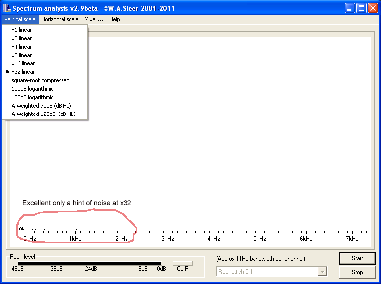
Below is
the theremin at the Null Point which reveals excellent power supply noise
filtering

This is the result of using
the 100R/1000uf filter
enhancement. This has the ground loop
filter between the finale theremin
or pre-amp output and the computer sound card
input. The theremin is set at the Null Point.
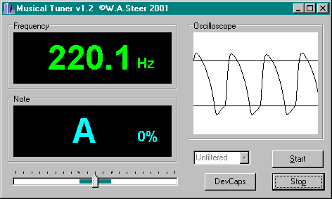
Download
these two basic yet brilliant programs - Freeware by William Andrew
Steer

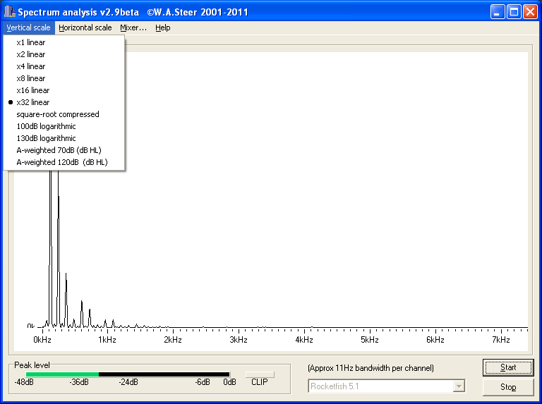
Below
is the Null Point the same as the graph above but the Ground Loop Hum Filter
is bypassed.

This is a noisy Null Point, the 60/120 hz loop-hum is obviously heard
and seen using this program
(clean it up with a ground loop filter)
What
does this sound like at the Null Point? hum.mp3
84k It's subtle but annoying, listen.
Appling the
R31 - C29 gives extra filtering to the Pitch Board oscillators. The
TRS stereo Jack is not installed on the pitch board. Three 1/2" holes with one in the 7809 area for the J2
cable to pass through. This creates a clean looking enclosure, no visible
controls, an idea proposed by
Dana (SewerPipe). On
a Phoenix board using the three Jacks at the bottom of the
graphic above, the audio signal must be passed from Output-2 to Input-1.
Plug in a short TRS stereo cable. A Y adapter cable works nicely
here. The purpose of this jump is to create a spot where an inline effects pedal can be added before the signal passes to Volume Control. The markings
HE on the printed
circuit board are being researched for an interesting sound effect by adding noise
feedback to the RF oscillators.
|