This
website will be active until
March 31, 2021
|
Always
use Ctrl-F5 to update this page
Phoenix
Construction Index
theremin2@oldtemecula.com
- My
original theremin design is not easy... only because we are human and
make mistakes -
..
|
The Vactrol VTL5C1 is
found on ebay

|
Here
are never done before Phoenix Theremin concepts
1. The Becker Electrodeum is a parallel tuned electrode
or Pitch Antenna for ideal Pitch Field Linearity.
2. The
use of L3 - 3.3 mh
choke to sense the inductive field from coils L1 & L2.
This approach eliminates the need for buffer components with more
control over the audio wave shape.
3. The use of
the VO618A opto-isolator feedback with the 600 ohm 1:1 transformer to
enhance the sound.
4.
Thermal Drift Control - This is done with Pot-3 by balancing the
voltage drop across both transistors. Most drift comes from the PN
junction capacitance.
-
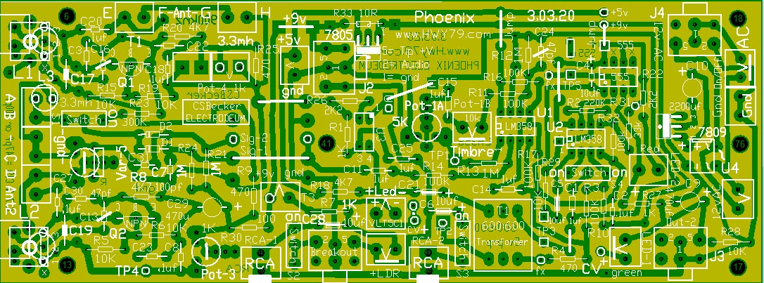
View Latest Updated Phoenix Board -
- Someone Else's
Good Webpage -
|

Click on Picture to
Enlarge
A $75 single board construction can be either a Pitch Board or Volume
Board
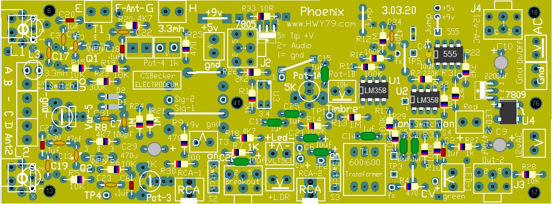
The 10
light tan capacitors on the left side oscillator section are
47pf,
except C7 & C31 are 100pf,
C17-10pf,
C19-Empty
Graphic of
Actual Parts Locations
3.03.20
|
|
Latest Board
Below is the Latest Board
with Every Modification
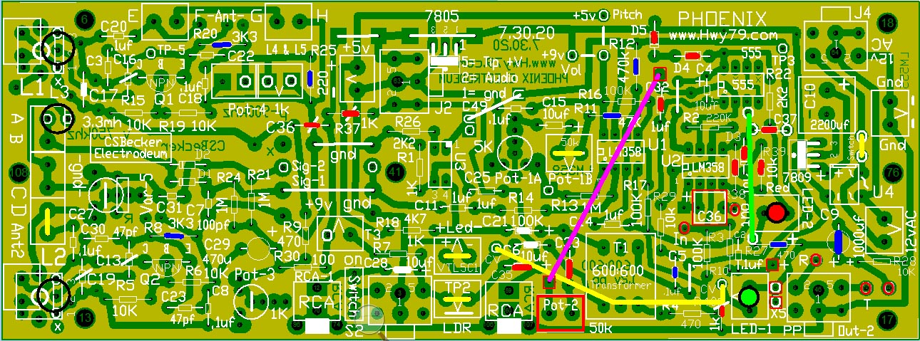
Click on Image to Enlarge
Image above the
long yellow wire is on Volume & Pitch Board, Add switch on Volume
Board on yellow wire for Mute.
Pink wire with
Pot-2 50k Timbre1, Pot-1b 50k both Timbre2 on Pitch Board only.
Experimental
The green wire is on both
Pitch & Volume
Components not on
the original 3.04.20 PCB are Marked in Red
The Blue
indicates a value change.
- Every yellow
line must be a wire jumper or the actual component to work properly -
<=
home
.
