|
If
you do not get earth ground at the wall receptacle it gets
challenging. Some people get earth ground through their audio
cable connected to an amplifier with a three
prong power plug.
This last method prevents you from using headphones as no earth
ground would be available. A Y-adapter at the theremin and leave
one side plugged into a turned off main amplifier with a three
prong plug
could work. If
you use a 12 volt battery (2
x 6 volt Lantern Batteries)
you could wire a three prong plug with only the wire connected
to the green ground terminal plugged into a wall receptacle.
Each board draws less than 30
ma. If
you are busking,
for earth ground drive a 3' or 1 meter metal rod into the soil
all the way so no one steps on it. Then dig around it and use an
alligator type clip to attach to it. Leave it there for
next time. (flowerbed) Earth
ground is
important because the theremin works with radio
wave energy
(RF) that will distort the sound if it has no way to leave the circuit
board. Yes your hand is a capacitance
effect but
there are many effects involved.
- when using
both boards together, do not
hook up power to both boards, use the J2 jack -
When first
connecting power to the board monitor the current for overload
indicating a mistake.
Power
Supply: For power the Phoenix is well filtered
and can use 12
volts AC, DC or a Switching power supply.
The two boards use less than 60 ma total and can drive a low
current accessory. Use a power source of 500 ma
or more, you
must get earth ground from somewhere. The
original home page lists many
components and things for your theremin build.
.
Board
3.04.20 Modifications
|
Fix
#1
Fix #1
This
is corrected on board date 4.14.20 and later
Do
this before stuffing parts
The 3.04.20
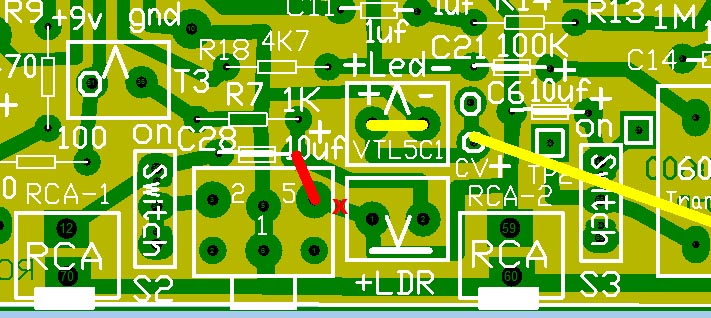
board needs a modification, cut the copper at the red
X with a razor blade. See PCB image at Fix #2 below
After the
parts are stuffed then add a jump wire across the pads with the red line.
This allows controlled audio
volume out the
breakout TRS jack on the left side of LDR.
Audio
and Power can pass board to board through the TRS J2 jack
using a TRS cable.
|
.
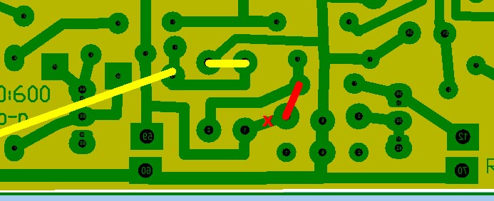
This is
viewing the board from the bottom side. Also view "Jumper" in
image below Fix #2.
Use a
drill bit in a drill or razor blade to break the x
copper
connection. Solder a wire across the pads of the red line
after you
mount the parts. Do
this before you stuff the board
|
Fix-2
Fix #2
Do
this before stuffing the parts, see photo below,
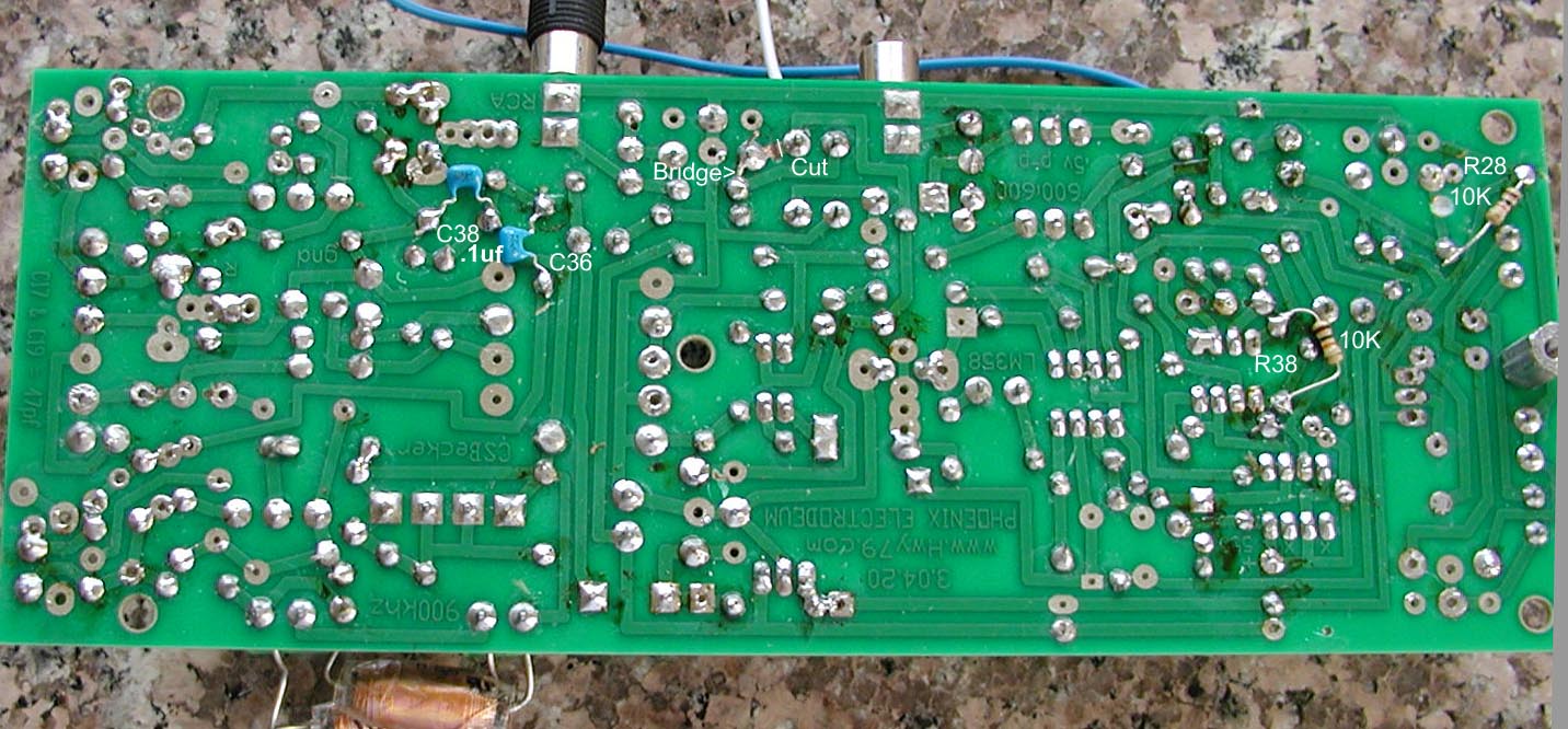
at "Cut" use a razor blade to break the copper track.
Study board bottom against that picture. Use a marker, place a
black dot at spot. Back
to Index
Do these fixes after the board has been stuffed.
When the green
LED-1 is ON the
Vactrol should be passing an audio signal. The
CV+ to CV+ jumper wire must be installed seen as the white wire
on the actual board. Added to this wire can be a Mute Switch.
There
is a solder bridge across IC pins 1 & 2 near R38, Do this on
Pitch board, Volume Board I do something different. Other than
that both boards are the same. Pitch Board only uses 600:600
transformer while the Volume Board only uses the Vactrol.
Before
board is stuffed (see
Fix #1 above)
use
a razor blade or drill bit to break the copper trace between the
two pads where it says Cut.
Click on Picture to
Enlarge
Bottom of
3.04.20 Pitch Board as of 8.20.20, Volume Board does not have
solder bridged IC pins 1 & 2 by R38
C38
is across C29- 470 uf &
C36 is across R9- 470 ohms &
R38 is across U2 pins 4 & 5 &
R28 is C9 plus side to ground to drain the charge on the
capacitor or it will latch up the 555.
Fix
#3
Fix
#3
Do
this fix "after"
the board has been stuffed.
When the green
LED-1 is ON the
Vactrol should be passing an audio signal. The
CV+ to CV+ jumper wire must be installed or attach a Mute switch
between here with wire
leads for a SPST switch.
Add a 4.7k resistor to
the two pads the red line touches so the green LED Off
at Null. (wait
on doing this)
|
| The
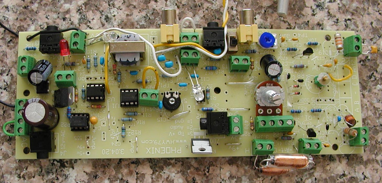
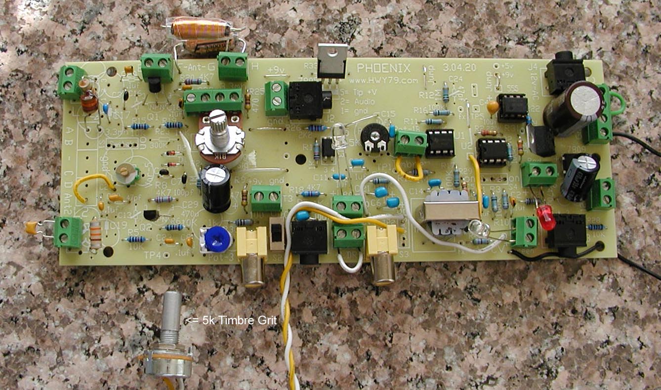
yellow & white wire is Audio Out to my scope probe
to hang on. The green jumper wire on the lower left
corner closes the switch terminal contacts to the TRS power jack.
The
longer white wire is for the PWM to the Vactrol. The
green terminal on the left of the white wire is temporary
bypassing the uninstalled Vactrol. This allows the LED's
to work.
The C19
capacitor under the L2 is not mounted or
used. L2 is in the upper right corner of the
picture, looks like a big resistor. Try different values
of capacitors in the green terminal to the right side of L2-330uh
coil.
Start with 22pf then 33pf, etc. Tune the variable
capacitor and see if you hit Zero-Beat. Return
to correction 3.
index
page.
|
-
Right click mouse, click on "open image in new tab" to
get a close up views -
Fix
#4 Component
Value Changes, all on the left side oscillator section
Resistors:
R8 & R20 emitter resistors was changed from 4.7k to 3.3k
Capacitors:
C17 changes from 47pf to 10pf,
C22 changes from 47pf to 100pf
Inductors:
L5 3300uh
was added to the Volume Board antenna/loop side, this must be of the high
current type
like L4. Pitch Board setup is 330
uh with 4.8 Ohms resistance max for higher
Q
When
I design I watch her waveform on an Oscilloscope. All of these
changes fine tune her Classic sound or her natural voice that
begins at the antenna and has been illusive for 100 years to
most designers.
Issues
For Study
PWM
PWM -
Volume Control
setup demonstrates
a weak PWM, the waveform is solid throughout its
frequency range. In previous builds using IF Transformers the waveform would change
with the frequency change and some how changed the offset of the
waveform. It was rather scrappy but it worked. Needs
Study
The Vactrol LED
terminal + -
may be backward? If
so Vactrol will be mounted upside down.
Mount a LED on
the LED side of the Vactrol green terminal in place of the
Vactrol when experimenting.
It was more triangular and would
cause the signal DC offset to shift with frequency, similar to a
triangular wave form rising above the scope dc center line. Need to get back to this. Needs
Study
Idea: This
schematic looks promising.
(will
breadboard this circuit, apply it in the C1-1uf area in
place of S4.
I need the
offset to drift .4v to the negative side with a 0-1khz
response
-
a negative .4 volt deflection would be better than none -
Experimentation
will demonstrate the best approach. See Switch S4 below - Visit
How the Volume
Control Works
Switch S4
Switch S4
is not
needed. Where S4 was wire jump the center switch pad to
the right side switch pad which is Pin-3 of U2 LM358. Then jump Pin 1 & 2 of the
LM358
also with a deliberate solder bridge. (Picture
Coming)
LED
LED - Mouser
only carries the 3mm size. I prefer the 5mm and a bright Mcd.
Green
LED-1
remains
ON when sound is passing through the Vactrol is ON. Needs
Improvement
Pot-1b 100k is in
series with Pot-1a 5k, this is for fine Timbre or
Volume peak
trigger adjustment. This controls how much skew is on the upper
side of the audio wave form or even harmonics are introduced.
This can be a jumper wire instead of a Potentiometer while
diagnosing the build. Good
On the Volume
Control setup the L4-3300uh
Pitch side tuning
choke should
"not" be connected.
4.17.20
This needs
study with the addition of L5 3300uh high Q coil.
Electrodeum
Electrodeum
4.15.20
Connected the Electrodeum
and it distorted the audio wave shape. My first impression it is
loading down the L1
oscillator and not resonating in harmony with it. The only
change from previous builds is the fix ferrite coils. When the
Electrodeum works it is like On or Off when it comes to
linearity. There is no almost linear, it either works or it does
not.
Higher-Q
L1 & L2 coils needs to be tried for driving
the Electrodeum.
Electrodeum
Observations: Needs
Study
When I substituted
the Electrodeum with a 10pf capacitor to ground it stopped L1
oscillation.
If the L4
the antenna 3.3 mh choke is not a high current (High Q)
the Electrodeum does not work.
I need to test a Higher
Q L1 330uh
coil, another type is seen in the pictures next to the antenna
side of the board.
The resonant frequency of
L4-3300 uh in series with a 10pf capacitor to ground is 900 kHz.
Using a scope we
may be able to tell if the Electrodeum is functioning correctly
by sensing the antenna voltage? At the antenna should be 30
volts or more using very high impedance probe.
The
Electrodeum could be capacitive coupling back to the L2
oscillator.
4.17.20 Need
to test the EWS pitch antenna with the L4
3.3mh in series
as most will not have the spring coil. The Phoenix fits inside
the EWS wood box. I do like the idea of a fat telescoping pitch
antenna. This allows external adjusting to the environment and
keeping Pot-4 for Zero Beat centered. Need to test linearity in
this approach.
Thermal Drift
| Thermal
Drift:
In solid-state drift is caused by the slightest imbalance between the two RF oscillators, to be more specific mostly the difference
is in the behavior of PN junctions.
The drift effect is exaggerated by temperature change caused poor design internally that allows a heat source like transformers, regulators and too much design current flow; this is what causes the “unnecessary” warm up period. Then there is the effect of the outside room temperature changes. Solid-state theremin circuitry should always be at room temperature On or Off.
All graphs should choose the same single note like A4 440 Hz and graph frequency change against a highly accurate thermometer. This should be done “without” the Pitch Antenna connected as you only want to monitor the circuitry for stability. The antenna will add its own effect and why using a telescoping antenna is a better idea though I would not use one as I think they look too whippy. There are other ways to add small changes to the length of the Pitch Antenna to balance it against the
environment background.
My best results over the years could hold onto the same musical note over a 5 degree F room temperature change. In other words I set the musical note to A4 the night before and wake up to my theremin still singing on A4
440 Hz or very close when I got out of bed in the cooler
morning.
Surprisingly Vacuum Tube theremins have less thermal drift than solid state.
9.05.20
The
first thermal drift test is done with the antenna
disconnected. After that proves solid then redo the test
with the Electrodeum connected 1/4 the distance from the
bottom of the spring coil which has demonstrated the best
drift resistant connection.
Test
below with Pitch on the proper side of Null or Zero Beat
-
Room temp decreases and pitch goes up,
- turn Pot-3 - a bit CW to
reduce resistance -
-
Room temp decreases and pitch goes down, turn Pot-3 a bit
CCW to increase resistance -
-
Room temp increases and pitch goes up, turn Pot-3 a bit CCW to
increase resistance -
-
Room temp increases and pitch goes down, turn
Pot-3 a bit CW to reduce resistance -
Full CCW max resistance of
Pot-3 100 ohm. Pitch rises as room temperature drops is
wanted.
When
ideal the
musical note A4- 440 Hz will remain with little drift over a room temperature change of 5 degrees F.
|
The transistor PN junctions have capacitance that
varies with the voltage across them and temperature changes, similar
to a Varactor. The goal is to balance the behavior of the two
transistors so they behave as identical as possible in the
circuit.
The next area of
drift is the Pitch antenna's capacitance relative to the environment.
This is where a telescoping antenna comes in handy. Stretch or
compress the antenna to keep zero-beat centered on Pot-4 which
used for fine tuning.
Pot-3
is added to balance the voltage across both transistor PN
junctions in the
oscillator section. This is for thermal drift control. The very
low current through the transistors allows this to work. Needs
Study
My concern is the
Var-5 variable capacitor could add imbalance and cause
thermal drift?
I noticed once the pitch raced up or
down over time while sitting idle. Replacing squirrely
transistors with another set should eliminate this. Using transistor
sockets might
be wise to find the best transistor combination.
Another cause of
racing may be mechanical
like a loose capacitor in the L2 green terminal or Pot-3 or Pot-4 are defective or
may need a
shot of DeoxIT®
Fader F-Series –
Contact Lubricant for Conductive Plastic Faders and Controls
. (do
not use WD-40)
Microphonic
effect when tapping the board was cause by the capacitor in the L2
green terminal not being secure.
When tuning the Variable
Capacitor and
it seems like the Null or Zero beat point is in the same
direction you are on the edge of the capacitors range. You need
to add a bit of capacitance (3.3pf ?) to one side or the other
to better center the variable capacitor. You want to be at
Null or Zero beat
when the
variable capacitor along with Pot-4
1k is set at
half way.
The sweep range of Pot-4
can be reduced by adding a parallel 470 ohm resistor at R25
on the right side of the Pot-4
green terminal. When experimenting I like to work with a large
range.
A
grounded
shield above or below the oscillator
L2
section may reduce
distortion
from Pitch Antenna capacitive feedback and blocks 50/60 Hz hum. Placing
the PCB against a wood surface can cause issues. Needs
Study
Don PB here is
your original 2013 schematic
and here is latest 2020 schematic.
Future
Ideas:
4.16.20
Diode D2
mixer diode is for a future experiment. Two channels could be
taken and shaped independently using a second Audio section of
the board and be true stereo or mix back together for a fuller
sound. Needs
Study
Develop
the circuit for rapid ON with Volume hand so notes can be popped
ON with a swift movement of the hand upward from the volume
control loop. This triggering could also briefly increase the
amplitude of the audio signal a better pop-on effect. Volume
Enhancement concept. Needs
Study
Another
way is to touch the volume loop as in my design of Volume
Control this would stop the oscillator from oscillating and have
a similar effect. Currently this last approach is a bit sloppy
on recovery. Needs
Study
|