|
- This
project is the true meaning of serendipity -
| Do not
substitute earth ground for a stretched out cable on the floor.
With an analog theremin that will prevent you from having the
fullest Classic Theremin sound. In digital theremin's this is
not so important, listen to how they sound in comparison. I will
post a scope picture sample of the same waveform with and
without earth ground. |
4.10.20
Today I am
setting up a new laptop computer I bought six months ago as a back up. I
ordered and waiting on a USB sound card with Microphone input and Audio
output. It may also work as a headphone amp. This comes from China but
might ship out of Pomona CA - I installed Audacity to record what I hear
against what I see on the scope.
Once again
as so many times before I
notice an odd unexpected behavior.
I see the excellent Vocal wave shape on the scope, then flip a switch
and the wave shape takes on a new character of what I think might be closer
to a natural Cello sound. (see
next image down) This could turn out to be second timbre knob.
Classic Sound Page
Good Info
It is U3 an
optical isolator & T1 a 600 ohm 1:1 transformer working together
with feedback to get this waveform. The first time I found it was using
a vacuum tube and 1N914 diode mixer/detector and it would not show up
again for weeks. This circuit should be correct on the schematic.
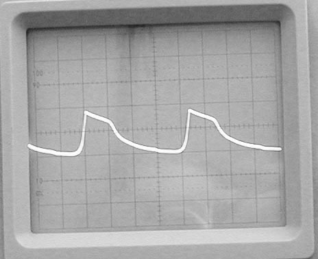
.5 msec/div
.5 v/div
This is an
excellent Vocal wave shape as of 4.10.20
The skew
on top is the even
harmonics, the lower
droop is the deeper throaty sound
| 10.23.20
The p-p voltage on the secondary of the audio transformer is
between .7 and 1 volt for the beautiful sound. It is possible to
drive the voltage to 3.5 volts p-p with clipping in the Op amp
powered at 5 volts, it will look similar but will not have the
sound your are after. For me the sound has always been elusive.
Does circuit temperature have something to do with it? |
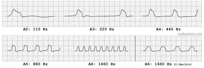
These RCA wave shapes are from master builder Andrew Baron's
RCA Registry webpage.
Read what he states creates a beautiful sound.
Notice the RCA 880 Hz wave shape, the RCA 220 Hz flat bottom creates the
low end buzzy sound. |
.

|
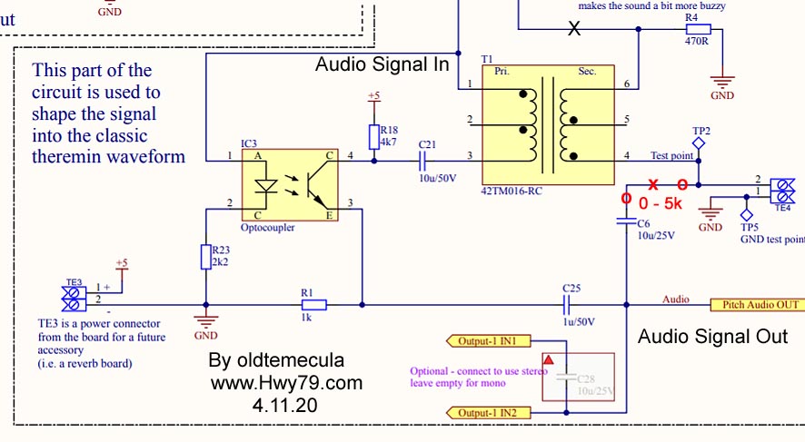
This is the
circuit that creates the wave shape for a beautiful Vocal sound. A
switch break at the red x
with a 5k
potentiometer inserted allows an adjustment of Sine Wave at 0 ohms to
Full grittiness at 5k. This should work with any theremin's 1 volt p-p sine wave
output including vacuum tubes. Like pitch preview it needs to be before
the volume control.
The Opto chip U3 V0618a works in conjunction with the
600 ohm 1:1 audio transformer
to control the skew at the top of the wave shape.
This is where the even harmonics are generated. Using the
higher voltage MPSA42-AP
transistors and the sluggishness RF detector circuit
with minimal current flow creates the
lower more throaty side of the vocal sound.
An oscilloscope should view the
audio signal at TP2 for the real and
desired .7 volt p-p wave shape.
I
was aware of this ten years ago but it seems we are all stubborn
at TW, no one listens and we all do our own thing. The Thierry
Bass Mod should be
redesigned so it has the low end and the upper Vocal
side. -
People could stop spending big money for beautiful sound - |
Two Timbre
knobs are possible. Sine to Vocal, Vocal to Cello 'ish and what's in
between.
I am in suspense
of what has been revealed, no sound for even me till I receive the sound card 4.17.20
With the
on board S3 switch you can select your Vocal sound or pre dialed in
Gritty sound.
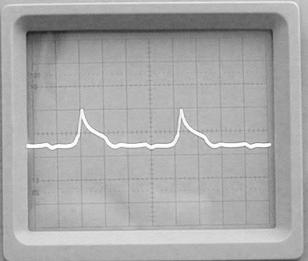
.5 msec/div
.5 v/div
Ideal Sine
Wave Whistle
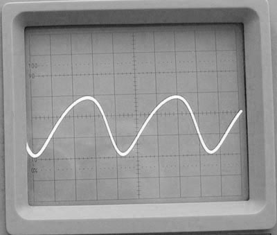
.5 msec/div
10 mv/div
|
Above this clean
audio signal is un-amplified measured after the detector diode, taken at
pin-2 of U1 LM358
My
original heterodyne method allows for the ideal mix, shape and amplitude of the
audio signal after the detector/mixer D1 diode. I can increase the raw audio signal amplitude up to 500 mv, not desirable.
|
.
.
- above
these two lines is the new build progress as I go, build
started 3.27.20 -
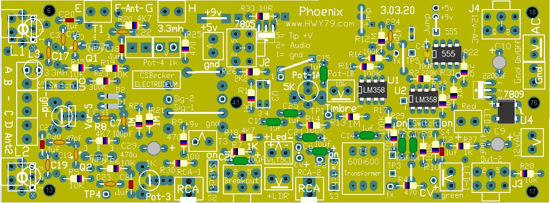
Mouser
Parts List
List is for a
Single Board Construction
Always
Check Parts List For What is Out of Stock!
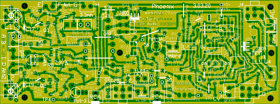
Graphic of
Actual Parts Locations
3.03.20
This single board is switchable, either Pitch or Volume, two boards
needed for theremin.
A small
grounded metal shield is place
over the L2 fixed oscillator section to keep the Electrodeum antenna capacitive
feedback from interfering or distorting the wave shape. It also
blocks 50/60hz from being picked up.
Fixed
ferrite coils can be used with a trimmer Cap.
A
replacement for the original Timbre adjustment is using a small
resistance at Pot-b in
series with Pot-1a.
On the Pitch
setup Pot-1a
is between the LM358 sides a & b which determines the drive amplitude into the
audio transformer circuit. This is set about
1/3 the way at first and works in conjunction with Pot-5 the Timbre signal strength from the
oscillators. This combination in series drives the transformer circuit.
Pot-1b
is in series with Pot-1a, this is for fine Timbre adjust.
At test point TP3 above S2 next to the transformer the amplitude is kept low and should be
~ .7
volts p-p for the proper sound to develop. The ideal wave shape will be viewed
there.
On the Volume
setup the
RF signal for detection comes from the L1 variable oscillator or loop antenna side, off of the emitter of Q1 through R23- 330k resistor, this
is switched in.
Pot-1b is in
series with Pot-1a, this is for fine Timbre or Volume trigger peak
adjustment.
The
main purpose of the 555 is to drive the LED's which one is also inside the
Vactrol for the pulse width modulation PWM volume control. The C9- 470uf capacitor
averages this control voltage from the 555 which varies the resistance
of the Vactrol output cell which then audio passes through, controlling
the volume.
|