Website will be active until March 31, 2021

<= home  

Always use Ctrl-F5 to update this page

Phoenix ChrisB Oscillator

theremin2@oldtemecula.com

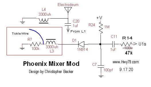
- Valery the modification below is for your Phoenix 2013 board -

This modification is for the Pitch Board and will allow you to break out of Null or Zero Beat below 30 Hz.

- I went back to using the IF Transformers on the Pitch Oscillators, maybe the Volume board also -

View Original Phoenix 2013 Boards         View Actual 3.04.20 Board 

I use the MPSA42 Transistors to test if the 300 volt junctions might have less PN junction influence, they also create a better wave shape for a slightly better sound. I did try 1000 volt transistors but they would not oscillate with my favored oscillator circuit design.

Below is the Original 2013 Phoenix Board - Updated 9.18.20

..

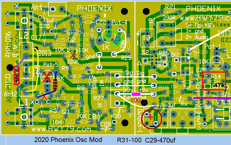
As seen above on the 2013 Phoenix board under the red X - Pot-5, C27 and R23 are removed from the board. Also the metal cans of the IF transformers are not connected to any ground.  

Mount your L3 in terminal B to Ant2. Mount a 100k resistor from Ant2 to the right pad of Pot-5 for earth ground. The center Pot pad will also work for ground.

In my graphic above I attach the tickle wire, a short wire 3" or 7 cm wire added at Ant2 on the bottom side of the board and feed it through a small hole you drill to keep it in place. Feed it through and wrap around. One end is not connected to anything.

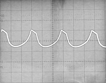
The longer the wire more signal drives the following circuits. Observe the signal at TP-1 or Pin #1 of U1a for proper wave shape.

R14 I reduced to 47k for a little more signal boost, may not be needed as tickle wire length also increase signal strength.

External Pot-5b is no longer used, instead for Wave shape I now use a Pot-1b 50k inline with Pot-1. This changes the sound by increasing the level through the Audio Transformer. 

Though I use the larger 3300 uh inductor like the antenna L3 inductor the smaller L3- 3.3 mh you have now will work. The L3 wire leads can break off so be careful.  
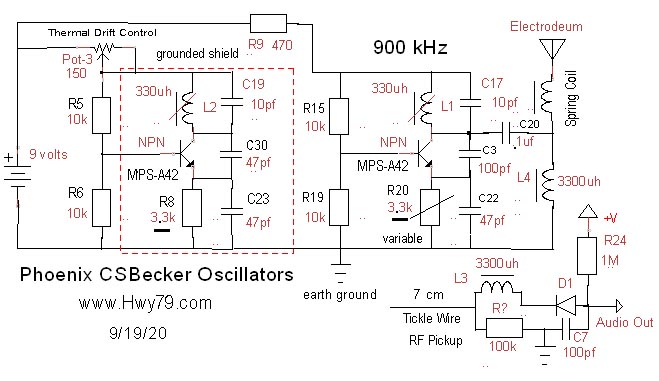

Thermal Drift Control is not on the Phoenix 2013 Board


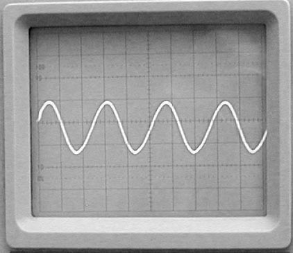
This is the ideal theremin vocal wave shape, 
from here we shape it as wanted.

L1 emitter signal is about 5 volts p-p. 
L4
is not attached

emitter dc voltage is 3.72v

L5- 330uh attached to 8" of wire

Voltage at top of R9 = 8.04v L3 resistance = 12.4 ohms

.

6.10.20 - I learned several things. Scope Test Probe must be set at x10 or it will drag the operating frequency 100 kHz lower when connected to the transistor emitter. 

The goal is the ideal theremin sound wave shape that has eluded most for over 100 years. Next is having the ideal sine wave with no low end coupling. The beautiful upper end audio is a reflection of the lower end wave shape.

.


The Radio Frequency Sniffer Coil

In the first test we are only powering the two RF oscillators. You must have the L4 & L5 antenna coils setup and have a direct connection to Earth ground, this is a must.

For your first antenna use an alligator clip lead dangling below the Phoenix board off the table. This helps avoid signal distortion from unshielded antenna RF/capacitive feedback.

In the picture to the left is how you measure the frequency of L1 & L2 to avoid overloading the circuit. Clip the extra 330uh coil/choke on the Mouser List to the end of your frequency counter probes. 

This is used as a RF sniffer when placed next to the L1 & L2 to get an accurate measurement of the frequency of each oscillator. Ideally you want L1 to be at 900khz and by adding capacitance to the green terminal next to L2 you lower its frequency to match the frequency of L1.

The Q1/L1 side frequency should be from 850 kHz to 920 kHz. (900 kHz is ideal) Measuring the frequency any other way will load down the circuit and stop oscillation. 

If you do not have a frequency counter it is possible to use an "analog" AM radio tuned to around 900 kHz and listen to the blank spots in the background static while finger touching the L1 & L2 coils. If the Q2/L2 oscillator is out of range of matching the frequency of the Q1/L1 oscillator you want to add or remove capacitance from the Q2/L2 side so L1 remains at 900 kHz. One thing that can cause this mismatch is the circuit are variables like the 10% tolerance of the coils, etc.


1.04.21 

Phoenix Thermal Drift Control

Pitch side must be 900 kHz to resonate with the Electrodeum pitch antenna. Volume side can be any freq that does not interfere in the Pitch sound. Thermal drift comes from PN junction capacitance which changes in how warm they are or the voltage across them. I use the
HFE or beta measurements to better match the two oscillator transistors behavior. 

Theremin design uses principles so sensitive they reveal phenomenon about components an electronic designer might never take into consideration. Two identical transistors and part numbers could be used and work perfectly together yet when choosing two other transistors from the same batch could drift all over the place. This is why I often say using computer modeling with theremin oscillators will most likely miss the mark in operation and reliability.

The Phoenix method of drift control shifts the voltage across the PN junctions or balances the reactance or Xc of both oscillators. 


Locking In Drift Resistance

Pot-3 with a parallel 220 ohm resistor from the hot side of the Pot to the center pin makes Pot-3 behave more like an audio taper. Set Pot-3 to it center resistance. Now adjust your pitch to 440 Hz. Now step away for a while until the room temperature changes maybe 2 degrees F. Your pitch most likely drifted off a bit. Now adjust Pot-3 to where the pitch is returned to 440 Hz. You have now created a anti-drift window that will hold your pitch at 440 Hz with a plus or minus 2 degree F  or a 4 degree F window. When the temperature exceeds this window all bets are off and drift may be exaggerated.

My vacuum tube theremin design had little if any thermal drift as they have no PN junctions yet there was heat changes around the large coils. My experiments with tubes is what revealed where most solid-state drift comes from.

earth-ground

- This project is the true meaning of serendipity -

- I am certain a poor earth ground has messed up many performances - 

Do not substitute earth ground for a stretched out cable on the floor. With an analog theremin that will prevent you from having the purest Classic Theremin sound. In digital theremin's this is not so important, then again listen to how they sound in comparison.

My two RF oscillators do not need buffering as they have no component connection between them, just earth ground. Between the circuits L1 & L2 magnetic fields will interact with one another. This can be controlled by the amount of current driving the coil and the distance between the L1 & L2 coils

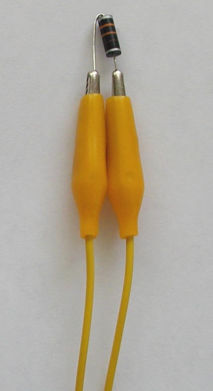
This L3 inductive pickup approach is unique and original. It allows me to control the amplitude and mix of the magnetic fields to get the best heterodyned audio wave shape out of the D1 diode.

The transistor emitter current determines the strength of the oscillator RF inductive fields. Too much you could get over coupling between the oscillators which causes unwanted distortion or locking the oscillators together above 100 hz.

Nice LC Frequency Calculator

I use the MPSA42-AP 300 volt transistors for a slightly better sound and thermal drift control. I changed the R8 & R20 4.7k resistor to 3.3k. If you must use a 2N3909 NPN you might want to keep the 4.7k for less range with Pot 4-1k. If you need even less swing when Nulling with Pot-4 1k the range can be reduced by adding a paralleled resistor, R25 with a 470 ohm. The fact that the MPSA42-AP reduces the Pot-4 range tells me the transistor will be less sensitive to thermal drift.

Thermal drift is reduced by the choice of transistor and matching the hFE values. 


Visit the Special Pitch Electrode 
Electrodeum Pitch Antenna

This gives me the ideal Pitch Field Linearity

This was my first unique theremin discovery, I looked up to the sky and said "are you serious"

<= home

.