|
At first
separate the parts into separate baggies, Resistors,
capacitors, Transistors & IC, Hardware, etc.
- If I
sent you "silver coated wire" do not use it, does not solder
properly - Thanks Don
|
Read this first
- Modifications Made to
PCB Board-3.04.20
|
|
1.
None of the corrected holes
need to be drilled or the switches installed.
S1 is
eliminated
S2 could be a panel
mount toggle switch for mono/stereo otherwise it is not needed
for single channel sound into your computer. It seems to drive
the computer speaker woofer needs the ring connection.
S3
is eliminated
S4
is eliminated
S5
is eliminated
You might want to
enlarge the 2200uf capacitor holes with
the Mouser .040 drill bit but it will still fit in the snug holes.
|
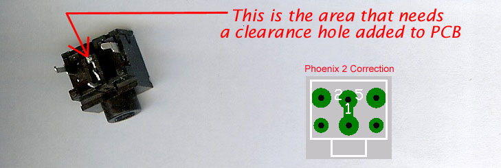
2.
You
might want to enlarge this hole in the four TRS jacks pads between 2 & 5 with a
1/16" drill bit
|
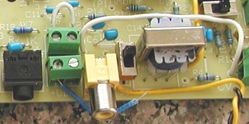
- the
blue wire is audio out for testing -
|
3.
Pitch Board
Only:
Fold the transformer mounting tabs underneath. The transformer center
wires are not needed and can be cut off and it can mount in
either direction.
Notice
how I offset the transformer to give room.
Mount
the big components last.
|
Update 8.18.20
Board
3.04.20
To find a
part use Ctrl-F
Cut PCB copper trace before starting. see
fix #1
-
Hello Sage, I hate troubleshooting but I will be your Pilot
-
Do
the best you can
At
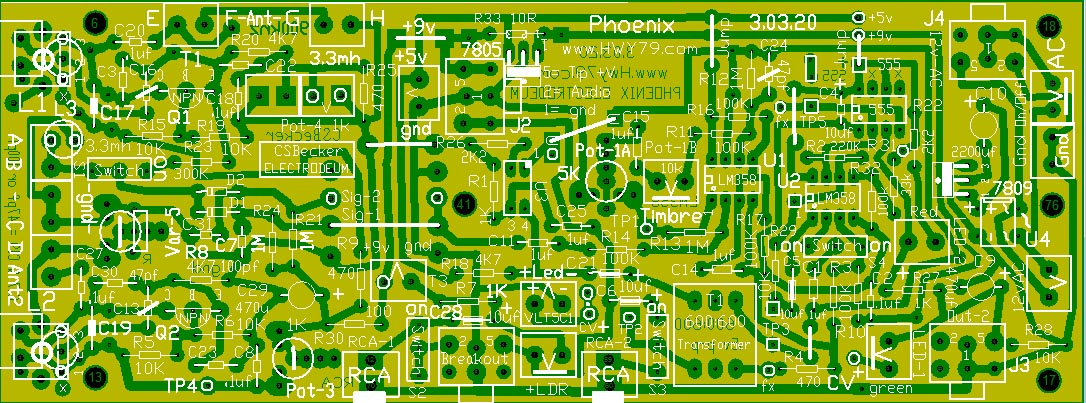
the bottom of every webpage is a see through 3.04.20
board image to better understand what is connected to what.
I
put the power supply on the Volume Board so it fits in the EWS
box, it is much better for it to be on the Pitch Board which is
the board you should start with. This
avoids issues with the TRS J2 board to board loose
jack connection disruption in the middle of a performance.
Print This
List: Stuff Resistors first, then Capacitors. In order from left to right.
Stuff
Sheet PDF 8.22.20 - Updated
Oscillator
section is the board 3" x 3" left side, Audio is the
right side 5" of the board.
| This
outstanding product keeps your solder pencil tip in
perfect condition Amazon |
Bold
parts are values changes, different than indicated on the 3.04.20
board.
Underlined
parts on PDF list are
not on 3.04.20 board, they are specially mounted after the board is
stuffed.
A Part
on the PCB or PDF
with a Line through it is not mounted at this time unless stated.
Mount
board resistors:
Osc: R5- 10K,
R6- 10k, R15- 10K, R19- 10K, R23- 330K, R8- 3.3k,
R20-
3.3k,
R24- 1M, R21- 1M
R25-
220
ohms, R9-
470
ohm, R30- 100 ohm
Audio: R37-
1K,
R7- 1K, R18-
4K7,
R26- 2K2, R1- 1K, R40-1K, 1K,
R41- 470
R33- 10 ohm, R14- 100K, R13- 1M,
R11- 47K,
R16-
100k,
R12- 470k, R17-
100K
R29- 22
ohms, R4-
470, R3- 100K, R10- 100K,
R34-
100K
see Fix
#2, R2- 220k
R38- 470,
R31- 33K, R27-
470
ohm, R32- 100K, R22-
2K2, R28-10K, R38-10K, R39-10K
After
resistors mounted, use an ohm meter to verify values. This
will save you time in the long run.
This
image is the latest as of 8/20/20,
the 3.04.20 board will need these modifications
Blue
is a value change, Red are parts not on 3.04.20 board, will be
added later.
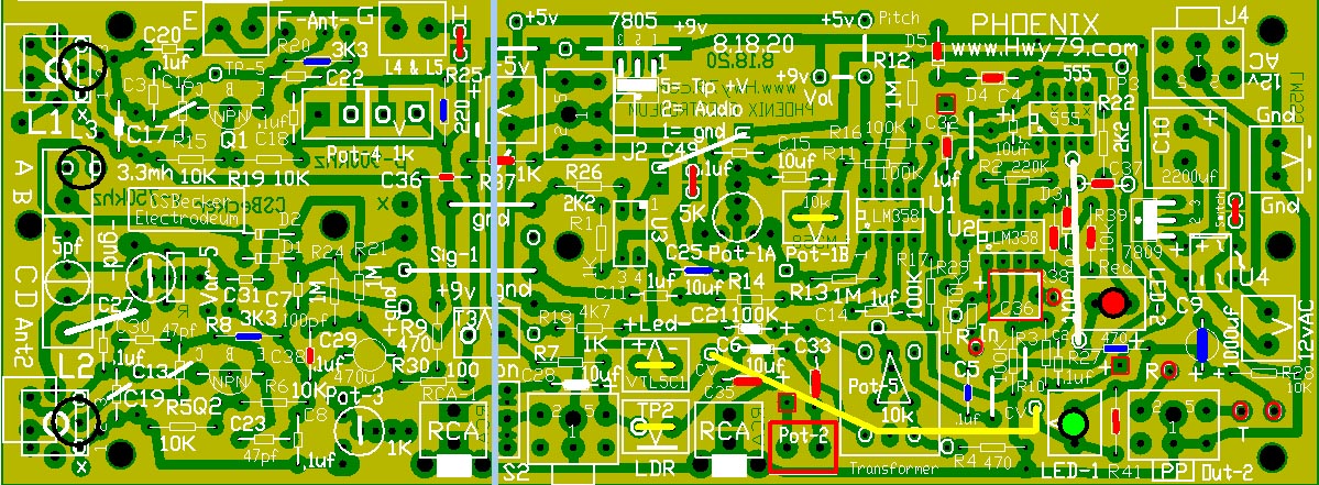
click on image to
enlarge
better
image to locate a part
8.22.20
That vertical gray line shows where the board could be cut apart.
There is an advantage in keeping the oscillator section separate
from the other parts on the board that generate heat like the
regulators. The oscillator section needs shielding to block interference
from Pitch Antenna feedback to the the L2 oscillator. This causes
un-wanted distortion in the audio signal or prevents you from
getting the deeper throaty vocal sound.
 |
Not
on the 3.04.20 board but on the latest updated
board are three of these. These are switch contacts that
can be used or bridged with solder to complete the
circuit. I will explain elsewhere in what they allow in
the Phoenix theremin design. |
Mount
board Capacitors: Update 8.20.20
Osc: C20-
.1uf, C3- 100pf,
C16-
47pf,
C17-
10pf, C27- .1uf, C30- 47pf,
C38- .1uf, C19
C13- 47pf, C23- 47pf, C31- 100pf, C7- 100pf, C18- .1uf,
C22- 47pf, C8- .1uf, C36- .1uf
Audio: C28- 10uf,
C11- 1uf, C25- 10uf, C21- 10uf, C6- 10uf, C49-
.1uf,
C15- 10uf,
C35-
10uf
C33- 10uf, C14- 1uf, C5- 1uf, C1-
1uf, C37- 1uf, C4- 10uf tantalum
direction is markings facing 555 IC
C2- .1uf,
C32-
1uf,
C34-
1uf,
C26-
10uf (C29- 470uf, C9- 1000uf, C10-
2200uf ) <= mount
these last
330uh shielded coils
View Coil orientation in board photos before mounting
L1 & L2 542-8250-331K-RC
5.10 ohms SRF=7.3 MHz
Q=65
L1 & L2 652-9250A-334-RC
6.4 ohms SRF=6.5 MHz
Q=55
L3 3300uh L4 & L5 3300
uh, the
high current type, less than 5 ohms or it will
not work.
-
Now go to the Oscillators
to Complete and Test Them -
Pot-1- 5K
trimmer D1 & D2-
1N914 D3 1N914
D4 & D5- 1N4007
Pot-1b 10k
Timbre sine to vocal adjust panel mount Wave shape on the EWS,
Pot-5- 10k
Pre-Amp
Pot-3- 1K paralleled by
R9- 470 for thermal drift control,
Pot-2- 50K
Experimental, may not be used.
Pot-4- 1K paralleled by R25 220
ohms panel
mounted or use EWS 5k. Both Pitch Null & Volume Null
Mount the L1 & L2 coils after all the
Oscillator parts are mounted. Pitch Board = 900 kHz &
Volume Board = 750 kHz not critical. See coil mounting angles in
picture. View
Coils
Mount
the L1 coil along with the L4 & L5
choke/coils along with a 10" or 25cm antenna connecting
wire for a temporary antenna. Then
dial in with extra capacitance in the green terminal next to L1
until 900 kHz or close +/- 20 kHz is achieved.
Start at a higher frequency
as the Pitch antenna will drag the frequency lower.
It
is better to not use probes in the oscillator section. Use the extra 330
uh, similar to L1 & L2 as a sniffer coil to sense frequency
connected to a frequency counter. View
Pic
The L2 side
C19- 47pf is not used, use a
felt tip pen and mark a line across it.
The L2 oscillator
will still work using the Var-5
variable capacitor but at a much
higher frequency. Try different values of capacitors (22pf)
in the
green terminal on the left side of L2-330uh coil
to match the L1 oscillator frequency.
Tune
Var-5 the variable capacitor and see if
you hit the sound of heterodyning and then Zero-Beat at ~ 900
kHz on Pitch Board.
This will need re-adjustment when the Pitch Antenna is installed.
Using
the 5pf variable capacitor from Amazon makes hitting Zero Beat
much easier.
An oscilloscope
works best for monitoring the ideal audio wave shape. Take the audio signal from
TP-2 or the left side wire
on the transformer next to the board edge. The audio can also
roughly be monitored with an "analog" AM Radio
listening for the actual heterodyned signal in the static around 900 kHz.
The goal on the Pitch Board is with L1 at "900 kHz" and adjust the
L2 oscillator frequency using a specific capacitor value in the
green terminal next to it to bring it home.
The
board you select to be the Volume Board has everything the
same except try for 750 kHz, this freq is not critical at all as
long as it does not affect the Pitch side sound. Also the Volume
Board uses U2a slightly different for a pre-amp to bring up the
audio signal level before the Vactrol.
8.24.20
Go to the Volume
Board for more board info
|
The
Phoenix will fit in a defective EtherWave Standard box
On the left
is a $24
new meter I purchased for this project. It measures
inductance, capacitance,
resistance
and important for thermal
drift control the ability
to measure hFE
which might be used to reveal a transistors sensitivity to heat or room
temperature change. Without touching the transistor so it remains at
room temperature measure the hFE
and lay them out as I
want two that are identical or close. Mouser sent the transistors on an
ammo strip, this is better than random grabs.
Two
transistors from the same batch can seem ideal but act all squirrelly
in theremin design, try two others. I believe the MPSA42
transistors I use have an advantage. Try and match their HFE number as
seen below.

I plan on
mounting the IC
sockets for all the
boards given away and give you the VTL5C1
Vactrol.
3.30.20

I packed all
the envelopes, they are black on the left. Should send by way of USPS tomorrow.
Funny that is USPS postal service driving by in the background.
I separate
the resistors, capacitors and inductors by placing them in their own
plastic baggie. As expected, missing from the parts list was the Pot-3
1k potentiometer. It is now on the parts list.
Also seen is
my $10 UV flashlight. This has several practical applications like see
the silkscreen and where the cat peed.
Before
anyone orders the parts list x2 it is better to let me finish stuffing
the board first.
3.31.20
Stuffing the single board
is about three hour project.
Discovered the four switches
have the wrong
footprint. An "oh shit" moment but figured out
a reasonable work around. You must drill eight holes in each board,
drill bit is with the Mouser order. I ordered the switches
from Jameco Electronics so I will also send those to you. The
original switches have been removed
from the parts list for now. View how to correct this on the Index
webpage. I
need to update Gerber Files and PDF Toner transfers.
Originally
the footprints at .1" was correct, they were out of stock until
August 2020 so I changed them.
4.01.20
Use a magnifying glass to
inspect your soldering and part values.
Because of
the footprint error
I had to substitute switches
from Jameco Electronics . Some
new holes need to be drilled. I will add a .9mm
drill bit to the Mouser parts list and "give" you 8 switches
to adapt to the two boards if you choose.
- None
of the switches are needed -
Switch S2
you might want as panel mount toggle so you can easily switch the TRS Jack
next to it from mono to stereo to feed into your PC. All the other
switches could be replaced with a jumper wire once you have a full build
and decide what works best.
I have
always considered my theremin as an experiment, that is why I use so
many of the green 5mm terminals. I like to make quick changes as
I develop things. Once you have a configuration you like you can use
soldered solid wire connections instead of terminals which is better.
The two green
terminals off the left side of the board allow me to test different
Inductor behavior before they are soldered permanently into place. They
also allow for a place to add extra capacitance when you want the Pitch
board frequency to lower down to be a Volume Board.
I use
inductor L3
to pick up the L1
& L2 magnetic
fields which are mixed in the D1 diode.
My two RF oscillators do not need buffering as they have no component
connection between them, just earth ground. Between
the circuits L1
& L2 magnetic
fields will interact with one another. This can be controlled by the
amount of current driving the coil and the L1
& L2 & L3 coil
orientation to one another.
The
transistor emitter current determines the strength of the oscillator RF
inductive fields. Too much you could get over coupling between the
oscillators
which causes unwanted distortion or too strong of a heterodyned mix.
This L3
inductive
approach is unique and original. It allows me to control the amplitude
and mix of the magnetic fields to get the best heterodyned audio wave
shape out of the D1 diode.
The D2
diode is a future
experiment. This
allows for a second channel using the audio section of another board and
mixing it back into the final audio for possibly a much fuller or
interesting sound.
4.03.20
On the
left side of the board are two other types of 330 uh chokes I want to test.
They mount on the
left side in the green terminals. I use an original method of mixing the
RF of the two oscillators using induction
coupling. This avoids
the need of any type of buffering to get the proper wave shape on the
low end.
The board
can still use 360uh IF transformers but variety allows more 330uh
workable inductors.
- Right
click and open the image in a new tab for a close up look -
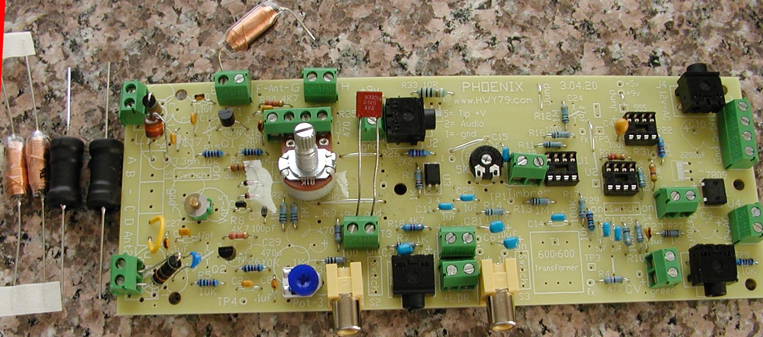
Notice the
components not stuffed on the board for this first
test. No big caps, regulators or
IC's.
- The
fixed ferrite coils that look like big resistors in the green terminals
on the left side I like so far -
The
capacitor standing up from the green terminal I use as a connection
point for a temporary 9 volts to the board, normally this is a
9 volt output for accessories. The green terminal directly above facing
to the left is 5 volts output for accessories.
When first
applying power, watch for excess current through the board, if things are good it is
about 2 ma.
I wanted to
change the emitter resistor from 4.7k to 2.2k to get more range at Pot-4. By accident I replaced it with a 22k so now I want to continue on
and see if anything of value will be discovered by this extremely
reduced emitter current, before I correct it.
- This
project is the true meaning of serendipity -
This first
test we
are only powering the two RF oscillators on the left side of the board.
You must have the antenna properly setup and connected. Earth ground
connected is a must.
| Do not
substitute earth ground for a stretched out cable on the floor.
With an analog theremin that will prevent you from having the
fullest Classic Theremin sound. In digital theremin's this is
not so important, listen to how they sound in comparison. |
Using a meter that can measure
frequency, take the signal from the ungrounded end of the L3 - 3300
uh choke. The Q1/L1 side frequency should be from 850
kHz to 920 kHz. (900
kHz is ideal) Measuring
the frequency anywhere else you will load down the circuit and stop oscillation.
On the L2
oscillator wrap a 100k resistor to the tip of your red probe and measure
your frequency at TP-4.
I use an "analog"
AM radio tuned to around
900 kHz and listen to the blank spots in the background static while
finger touching the L1 & L2 coils. If the Q2/L2 oscillator is out
of range of matching the frequency of the Q1/L1 oscillator you want to add
or remove capacitance from the Q2/L2 side. One thing that can cause this
mismatch is circuit variables like
the 10% tolerance of the coils, etc.
Nice
LC Frequency Calculator
In the picture,
lower left corner, you can see I
changed the yellow C19 - 47pf to the blue 39pf capacitor to raise the frequency
of the Q2/L2 oscillator slightly. Now I think 33pf + 22pf variable
capacitor on the L2 side with L2 choke. Always have the pitch antenna
setup as it adds up to 10pf to balance the circuits.
With the L2
choke soldered in place use the L2 green terminal for capacitor
substitutions.
For finding
the proper L2 frequency extra capacitors are added to the list.
10pf, 22pf, 33pf, 39pf, 47pf
I will put a red
circle around a few spots that are tricky with close soldering. The 10uf
tantalum capacitor next to the 555 socket has a difficult to see +
plus marking to get its direction correct. If backward it will short out
and the larger 10 ohm resistor next to the 7805 regulator
will overheat.
I use the MPSA42-AP
300 volt transistors for a slightly better sound and thermal drift
control.
I changed the R8 & R20 4.7k resistor to 2.2k. If you must use a
2N3909 NPN you might want to keep the 4.7k for less range with Pot 4-1k. If you need even less swing when Nulling with Pot-4
1k it can be
paralleled at R25 with a 470 ohm. The fact that the MPSA42-AP reduces the Pot-4 range tells me the transistor will
be less sensitive to thermal drift.
Thermal
drift is reduced by the choice of transistor and matching
the hFE values. Then balance the current
through the two transistors using the 1k Pot-3 at the bottom of the
board. At first set it half way so it matches the R9- 470 resistor value. With this method you
can actually reverse the direction of drift were the Pitch can drift in
the other direction.
The
natural theremin sound is a wave shape as seen on the scope with the proper bends and curves
here and there. It is not the mixing of saw tooth waves with sine waves
and what not, that is more like mixing noise.
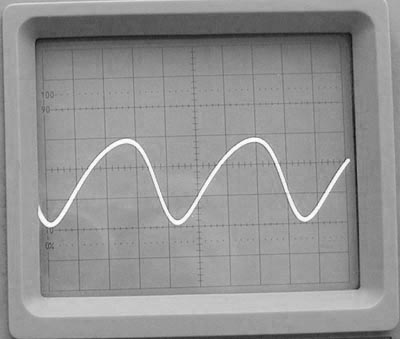
.5 msec/div
10 mv/div
This clean
audio signal is un-amplified measured after the detector diode, taken at
pin-2 of U1 LM358
My
original heterodyne method allows for the ideal mix, shape and amplitude of the
audio signal after the
detector/mixer D1 diode. I can increase the raw audio signal amplitude up to 500 mv, not desirable.
| 4.5.20
- I do not have the virus, rather a heart/lung issue caused by diabetes. I can barely walk from room to room, breathing
can not keep up. Trying to finish up my last version of our musical
instrument. It will be sent to the same artist who lives in the town
of the original 1919 inventor and friend of the Theremin
family.
I said 20 years ago that Clara's Voice
was a gift to me,
that is what kept me going. Jokingly I would say, ask Dorit
Chrysler if
she has it.
I am having fun, if ever you saw that movie "The Book of Eli", that is how I feel, I
must finish the journey in the West and write down what twenty
years revealed to me. Did something metaphysical happen along
the way, I will
leave that up to you to decide.
|
Visit
the Special Pitch Electrode
Electrodeum Pitch
Antenna
This gives
me the ideal Pitch Field Linearity
This was
my first unique theremin discovery in the beginning, I looked upward and
said "are you serious"
- above
these two lines is the new build progress as I go, build
started 3.27.20 -
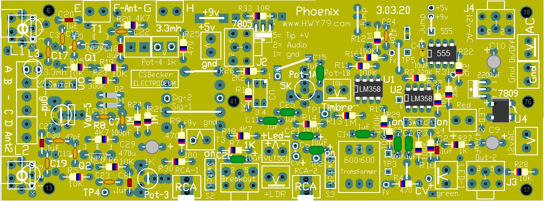
The 10
light tan capacitors on the left side oscillator section are 47pf,
except C7 & C31 are 100pf, C19 22pf
Mouser
Parts List
List is for a
Single Board Construction
Always
Check Parts List For What is Out of Stock!
.
|