|
visit
earth ground
|
I have avoided using variable capacitors until this last theremin build as I always thought being mechanical they would also add to drift.
Using the Var-5 variable
capacitor 2 - 18pf I
find it difficult to balance the oscillators for heterodyning as
it sweeps by Zero-beat too fast. The advantage of using a
variable cap is I can position the fixed ferrite coils perpendicular
so they have no influence on one another.
Amazon
has a simple set of variable capacitors and a blue
5 pf variable
could parallel the main Var-5 for fine tuning. You could
substitute the Var-5 on the Mouser list for the Amazon green
30
pf variable cap. Always make sure the rotor connection the screw
driver touches is soldered to the ground side.
* In theremin design
there are always trade-offs.*
I used the MPSA42 Transistors to test if the 300 volt junctions might have less PN junction influence. This still needs more study but stayed with them as they created a wave shape that mixed for a slightly better sound. I did try 1000 volt transistors but they would not oscillate with my favored oscillator circuit design.
* A test that needs to be done is find which is more stable? Vary the emitter resistance or use a low value variable panel mount capacitor and leave the PN junction voltage fixed.
The EWS drift resistance is no better than my approach. |
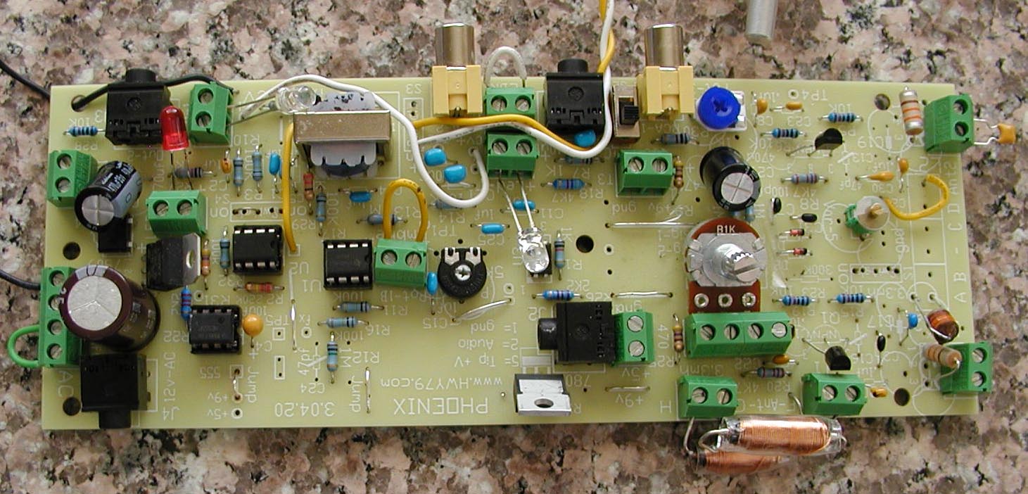
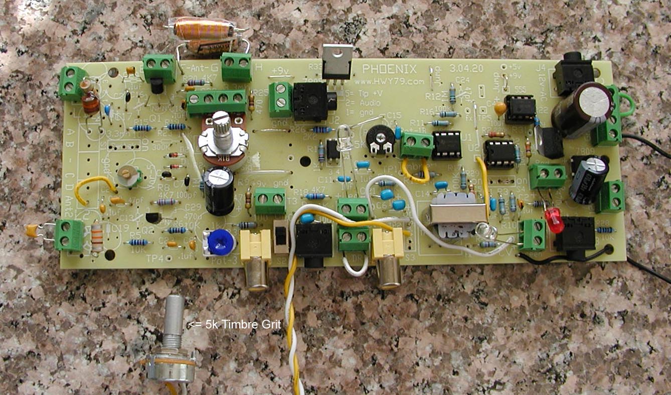
Notice the
orientation of the L1 & L2 coil on the left side, perpendicular
prevents them from interacting
- I went back
to using the IF Transformers for the Pitch Oscillators, maybe the Volume board
also -
View
IF Transformers Here
|
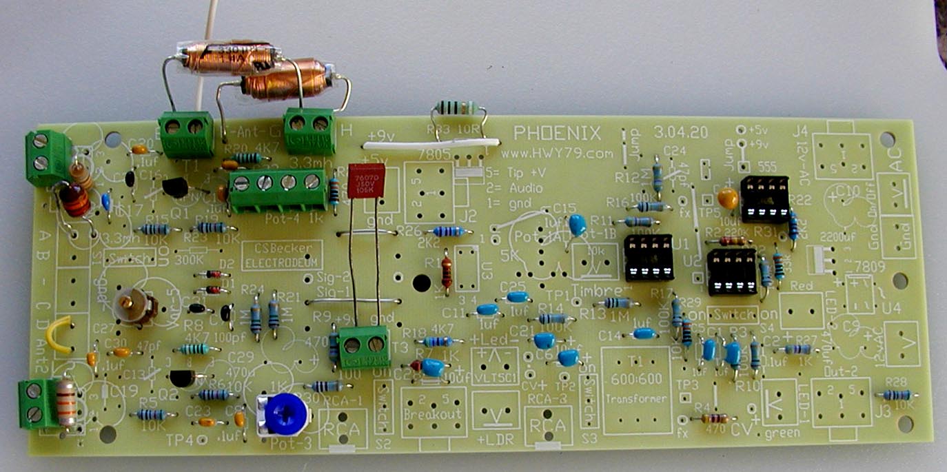
click on picture
to enlarge
The
long wires on the red capacitor I use to connect 9 volts.
Before power is attached you should measure
about 1.2k ohms
across this green 9 volt terminal. Regulated power supply
best, a 9 volt battery will work.
-
Finish stuffing the Oscillator Section as seen above -
The
variable capacitor Var-5 is 2-18
pf or similar.
The rotor part of any variable capacitor should be on the ground
side so touching it with a screwdriver does not affect it. This can sweep past Zero Beat rather quickly. Not necessary but
you could place a 5
pf variable cap
(Amazon)
in parallel at terminal pads C & D to the left of it. This
would be Var-5b.
Move the yellow wire in D to the pad to the right of it. Have the
rotor side of the variable caps in the ground side pad. Use an ohm
meter and touch the rotor or screwdriver section and then the
pins. The pin of zero resistance must be the grounded side.
On Var-5
Datasheet
C17- 10pf
is to complete the L1 LC circuit.
At the
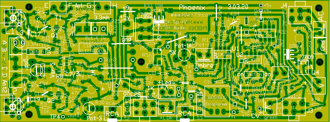
bottom of every webpage is a transparency of the parts
against the copper traces so you can see the connections. The
view is from the top of the board.
6.09.20
This
is the first Phoenix test, the oscillator section. Pot-3 1k
is
set half way
(blue on this
board). No
Pot-4- 1k needed in this test as R25- 220 ohms completes the circuit.
R25 in parallel with Pot-4 allows a 1k or 5k as on the EWS panel
to be used with a range of about 0 - 200 ohms for emitter PN
junction tuning. This is in series with R8 & R20 the
transistor emitter resistors.
Pot-3 balances the thermal
drift difference between the two oscillators by shifting the
voltage across the transistor PN junctions..
If the
C4 10uf
capacitor by the 555 is backward it will behave like a delayed
short circuit.
Notice
the L1 & L2 choke/coils are perpendicular to one
another. This reduces inductive field cross talk.
|
|

L1
emitter signal is about 4
volts
p-p.
L4 is attached to ground |

L1
emitter signal is about 5
volts
p-p.
L4 is not attached |
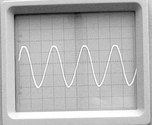
L2
emitter signal is about 7
volts p-p. . |
|
emitter
dc voltage is 3.72v |
L5-
330uh attached to 8" of wire |
emitter
dc voltage is 3.69v |
| Voltage
at top of R9 = 8.04v |
L3
resistance = 12.4 ohms |
Voltage
at bottom of C8 or Pot-3 = 7.99v |
| The
green terminal cap = ? |
This
is to be a Pitch Board |
The
green terminal cap = ? |
- Tomorrow
I will tune both oscillators to 900 kHz for the heterodyne audio signal
-
| 6.10.20
- I learned several things. Scope Test Probe must be
set at x10 or it will drag the operating frequency 100
kHz lower when connected to the transistor emitter.
Starting
frequency of L1 & L2 is about 980 kHz
which is ideal, a capacitor is then needed in the green
terminal next to it to drop down to 900 kHz.
L1 sine
amplitude is lower than L2 because R9- 470
ohm needs a .1uf
bypass capacitor to match the L2 amplitude. I have been
aware of this but never tested it.
For the Pitch
Board less amplitude may be better for no low end early
coupling and more amplitude for Volume Control to get
the PWM wave shape pulling.
L4 &
L5 do not drag the RF wave shape lower in amplitude on
the Pitch Board of 900 kHz, The sine wave shapes look very nice. On
the Volume Board at 750 kHz L4
should not be connected.
The goal is the
ideal theremin sound wave shape that has eluded most for over
100 years. It is not having the ideal sine wave or low end
coupling. The beautiful upper end of audio is a reflection of the lower
end wave shape..
I
forgot to mention that a 22pf variable
capacitor in series with
.1uf
is still 22pf, the
.1uf is transparent in the circuit.
|
Tuning the Oscillators
The
natural theremin sound is a wave shape seen on an oscilloscope with the proper bends and curves
here and there. It is not the mixing of saw tooth waves with sine waves
and what not, that is more like mixing unnatural noise.
.5 v/div
1 ms/div
|
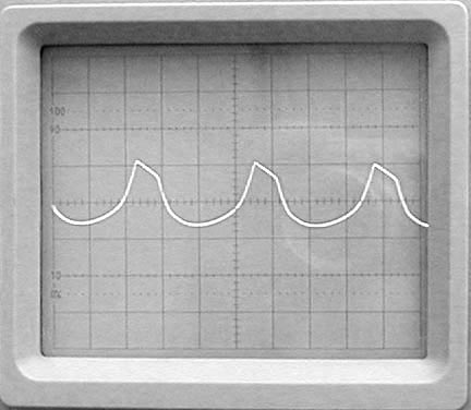
Perfect
(more
droop the better) |
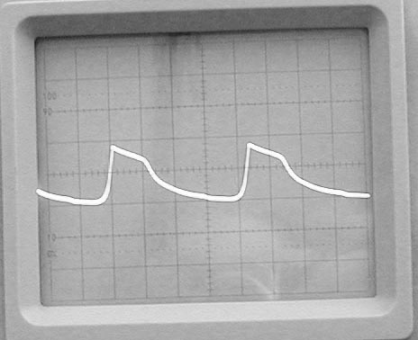
Excellent
(Vocal) |

Poor
(antenna
feedback) |
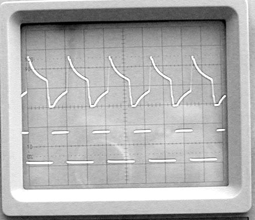
Over
Coupling for PWM
(Bottom
Signal Out 555) |
|
In
theremin design locking the oscillators at the Null
Point is a flaw more than a benefit.
-
To avoid audio wave shape distortion antenna orientation
and shielding are important - |
|
Use Ctrl-F5 to update this
Image
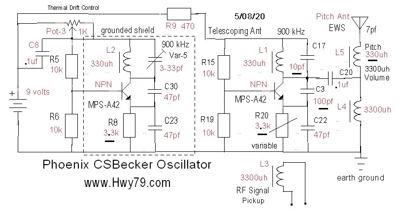
Having C8-
.1uf increases sine wave amplitude 33%, this is not
always desired. |
|
|
|
|
 |
-
Right click mouse on any picture, open in a new tab for
larger view -
Notice
in the picture to the left that I do not allow the board to sit
against the wood which has natural moisture in it.
Seen in the picture
above on the upper left corner that the L3 3300uh choke/coil
is leaning over toward L1, the distance determines the
RF signal mix strength. To close could pickup static noise
in the sound, seen on the scope and also the same static heard over the AM
Radio. L3
picks up the L1
& L2 magnetic
fields which are mixed in the D1 diode for the heterodyned audio
output. Your final frequency may need adjustment if a
strong AM
Radio Station
is in the area.
The two green
terminals off the right side of the oscillator sections allow adding extra capacitance when you want the Pitch
board frequency to be lower for a Volume Board. |
shielding
|
The
Radio Frequency Sniffer Coil |
 |
In
the first
test we
are only powering the two RF oscillators.
You must have the L4 & L5 antenna coils setup and have a direct
connection to Earth ground, this is a must.
For
your first
antenna use
an alligator clip lead dangling below the Phoenix board off the
table. This helps avoid signal distortion from unshielded
antenna RF/capacitive feedback.
In
the picture to the left is
how you measure the frequency of L1 & L2 to
avoid overloading the circuit. Clip the extra 330uh coil/choke
on the Mouser List to the end of your frequency counter
probes.
This is used as a RF
sniffer when placed
next to the L1 & L2 to get an accurate measurement of
the frequency of each oscillator. Ideally you want L1 to be at 900khz
and by adding capacitance to the green terminal next to L2 you lower its
frequency to match
the frequency of L1.
The Q1/L1 side frequency should be from 850
kHz to 920 kHz. (900
kHz is ideal) Measuring
the frequency any other way will load down the circuit and stop oscillation.
If you do
not have a frequency counter it
is possible to use an "analog"
AM radio tuned to around
900 kHz and listen to the blank spots in the background static while
finger touching the L1 & L2 coils. If the Q2/L2 oscillator is out
of range of matching the frequency of the Q1/L1 oscillator you want to add
or remove capacitance from the Q2/L2 side so L1 remains at 900 kHz. One thing that can cause this
mismatch is the circuit are variables like
the 10% tolerance of the coils, etc.
|
7.21.20
Phoenix Thermal Drift
Pitch side must be 900 kHz to resonate with the Electrodeum pitch antenna. Volume side can be any freq that does not interfere in the Pitch sound. Thermal drift comes from PN junction capacitance which changes in how warm they are or the voltage across them.
I use the HFE
or beta measurements
to hopefully better match transistor behavior.
Theremin design uses principles so sensitive they reveal phenomenon about components an electronic designer might never take into consideration. Two identical transistors and part numbers could be used and work perfectly together yet when choosing two other transistors from the same batch could drift all over the place. This is why I often say using computer modeling with theremin oscillators will most likely miss the mark in operation and reliability.
The Phoenix method of drift control shifts the voltage across the PN junction. My theory is the transistor bias values setup the transistor as a current source. Changing the transistor load (Pot-3 1k) shifts the voltage across this current source. The PN junction capacitance changes with temperature or the voltage across it. This is why varying the emitter resistor value can be used for fine tuning the oscillator frequency.
My vacuum tube theremin design had little if any thermal drift as they have no PN junctions yet there was heat changes around the large coils. My experiments with tubes is what revealed where most solid-state drift comes from.
earth-ground
The
Phoenix board
can still use 360uh IF transformers while other types of 330uh fixed inductors
can be used.
- This
project is the true meaning of serendipity -
- I am
certain a poor earth ground has messed up many performances -
|
Good
Earth Ground
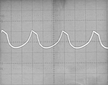
.5 v/div
1 ms/div
well
grounded is the ideal clean audio wave shape |
Poor
Earth Ground
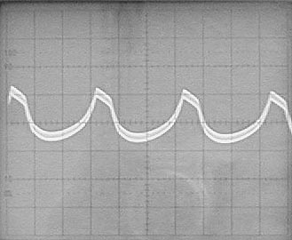
.5 v/div 1 ms/div
With
no
earth ground RF pollutes the audio signal, this also indicates a
poor Pitch Field response. |
| Do not
substitute earth ground for a stretched out cable on the floor.
With an analog theremin that will prevent you from having the
purest Classic Theremin sound. In digital theremin's this is
not so important, then again listen to how they sound in comparison. |
.
|
My two RF oscillators do not need buffering as they have no component
connection between them, just earth ground. Between
the circuits L1
& L2 magnetic
fields will interact with one another. This can be controlled by the
amount of current driving the coil and the L1
& L2 coil
orientation to one another.
This L3
inductive pickup approach is unique and original. It allows me to control the amplitude
and mix of the magnetic fields to get the best heterodyned audio wave
shape out of the D1 diode.
The
transistor emitter current determines the strength of the oscillator RF
inductive fields. Too much you could get over coupling between the
oscillators
which causes unwanted distortion or too strong of a heterodyned mix.
The D2
diode is a future
experiment. This
allows for a second channel using the audio section of another board and
mixing it back into the final audio for possibly a much fuller or
interesting sound.
Nice
LC Frequency Calculator
I use the MPSA42-AP
300 volt transistors for a slightly better sound and thermal drift
control.
I changed the R8 & R20 4.7k resistor to 3.3k. If you must use a
2N3909 NPN you might want to keep the 4.7k for less range with Pot 4-1k. If you need even less swing when Nulling with Pot-4
1k the range can be reduced by adding a paralleled resistor, R25 with a 470 ohm. The fact that the MPSA42-AP reduces the Pot-4 range tells me the transistor will
be less sensitive to thermal drift.
Thermal
drift is reduced by the choice of transistor and matching
the hFE values. Then balance the current
through the two transistors using the Pot-3- 1k
at the bottom of the
board in the oscillator section. At first set it half way so it matches the R9-
470
ohm resistor value. With this method you
can actually reverse the direction of drift were the Pitch can drift in
the other direction.
|
|
-
To avoid audio wave shape distortion antenna orientation and
shielding are very important -
Seen
below the
board mounted vertical with a vertical pitch antenna, this is ideal |
|
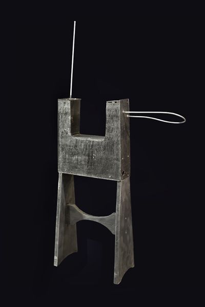
Original
build of Leon Theremin |
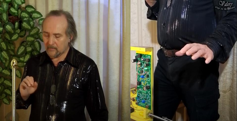
Valery
S in St Petersburg Russia, the original home of the Theremin
family |
Valery
S Performing
* * *
| 4.5.20
- I do not have the virus, rather a heart/lung issue caused by diabetes. I can barely walk from room to room, breathing
can not keep up. Trying to finish up my last version of our musical
instrument. It will be sent to the same artist who lives in the town
of the original 1919 inventor and friend of the Theremin
family.
I said 20 years ago that Clara's Voice
was a gift to me,
that is what kept me going. Jokingly I would say, ask Dorit
Chrysler if
she still has it.
I am having fun, if ever you saw that movie "The Book of Eli", that is how I feel, I
must finish the journey in the West and write down what twenty
years revealed to me. Did something metaphysical happen along
the way, I will
leave that up to you to decide.
|
Visit
the Special Pitch Electrode
Electrodeum Pitch
Antenna
This gives
me the ideal Pitch Field Linearity
This was
my first unique theremin discovery, I looked upward and
said "are you serious"
- above
these two lines is the new build progress as I go, build
started 3.27.20 -
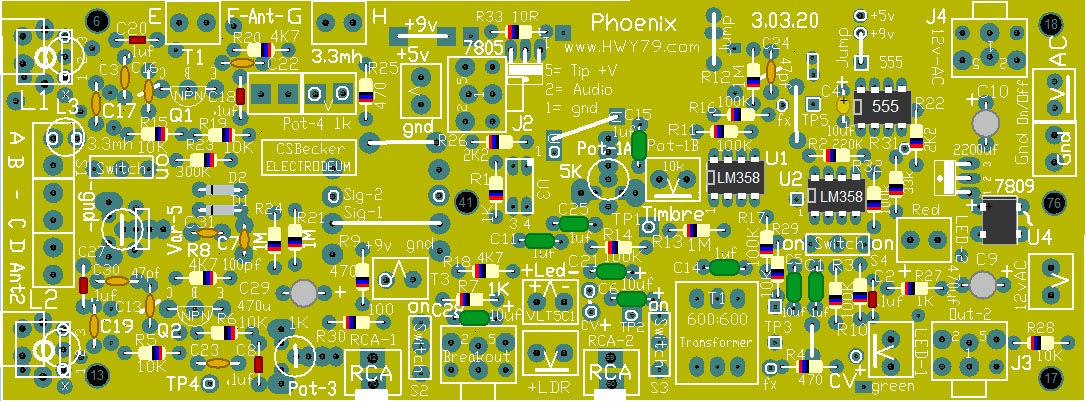
The 10
light tan capacitors on the left side oscillator section are 47pf,
except C7 & C31 are 100pf, C19 empty
Mouser
Parts List
List is for a
Single Board Construction
Always
Check Parts List For What is Out of Stock!
board-foil
.
|