How does the Volume Control work?
5.31.20
The Phoenix Volume Control is very sensitive. The insulated
connecting wire is slid inside the loop and not
directly connected to the loop.
This approach also protects against static discharge harming the
circuit. The length of wire inside the loop determines the
sensitivity of the loop. Start with about 8" or 20cm.
4.13.20
A variable wave shape from the RF oscillator section gets wider
and narrower dependant upon your volume hand distance and the
frequency it is at.
This signal is
amplified and drives pin-2 of the 555
which is a Schmitt Trigger circuit internally and squares off the wave shape for Pulse Width Modulation.
C9-470uf at the Null Point or Zero
Beat is fully charged which keeps
the internal Vactrol
LED ON because the 555
pin-3 is held High.
PWM is used to discharge the C9-470uf
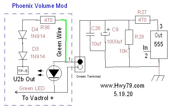
which eventually drops below the series green LED-1
and the internal Vactrol LED turn on voltage, the
Vactrol LED turns off, so does the sound.
The green LED-1
ON, in series with the Vactrol LED, works as an indicator that
audio sound is passing through the
Vactrol
internal LDR, it is at a lower resistance, it is ON.
LED-1
the green LED also raises the voltage level or trip point where the Vactrol
turns On or Off. The control voltage range or swing across the
Vactrol circuit is less than 1 volt.
When not controlling
the Vactrol, remove the green LED-1, you can take a 0v-5v
CV or Controlled Voltage out of
the 3.55mm TRS J3 jack used as TS.
Always use Vactrol VTC5C1
as the VTC5C2 and higher # are
slower in recovery and cause delay in turning off the sound off.
How to
improve the Volume response:
| Don
- The Vactrol is in series with a green LED that has a 2.1v
forward voltage. A 2.3v green LED was also added
to the list as this slight difference could make the
difference of a loud sound to a very quiet sound to be a
loud sound to an Off or no sound.
Where
switch S3 is located use a jumper wire across the
outside connections, avoid the center connection. This
way an audio signal can be fed into the RCA jack
next to it and volume controlled sound taken from the
left side TRS or the RCA jack.
For a
testing signal I feed the output of my portable FM radio
into the right side RCA jack. Do
not do
this through the TRS J2 jack as it is alive with
9 volt power.
Normally
when using two boards, Pitch & Volume, the TRS jack
J2 is used with a TRS cable to pass audio and power
between the boards.
It is
best to keep the power supply on the Pitch Board
as that R33 10
ohm
resistor next to the 7805 was added for short circuit
safety between the boards. If done the other way it
causes a slight Pitch shifting due to the small voltage
drop across it. |
 |
 |
|
Click
on Image to Enlarge
In
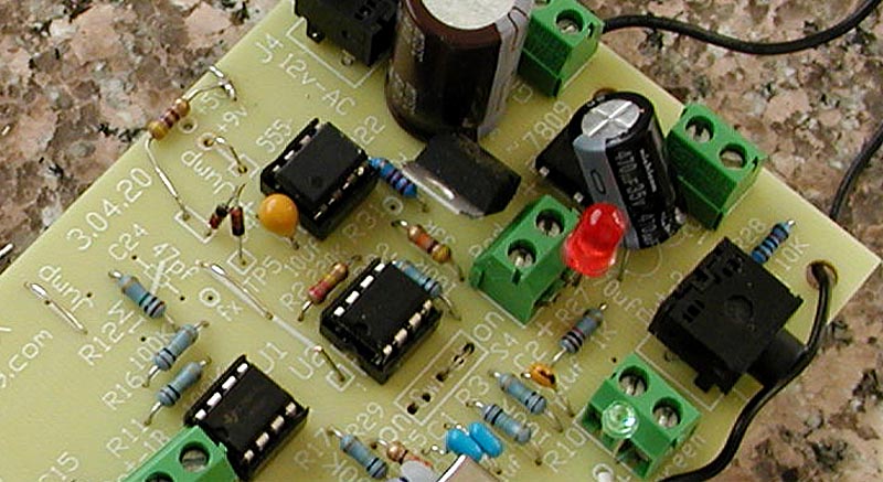
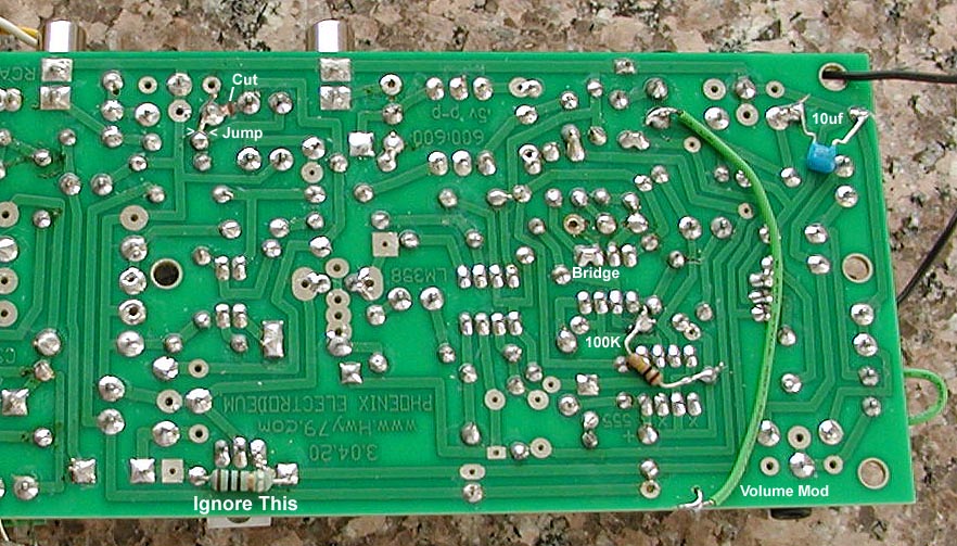
the left image above at TP-5 two 1N914 diodes and a 470
ohm resistor was added. In the right picture a green
wire passes the signal down to the green LED terminal.

|
Below is a
quick Volume Response Add-ON method
Experimental - Needs
Study
|