|
How to drill precise
locations for the holes

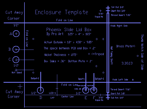
Template
PDF 194k
Print the Actual Size
Not every hole needs to be drilled Cut
away the two corners, "accurately" fold down on the line on three sides with
the text facing outward The
template is designed using a board space of .2",
if your standoff is taller add the difference above the +.
With the template in position, wrapped around the back side of the box,
center punch each hole of choice at the indicated + with a nail or center
punch, tap with a hammer. Remove template and drill at the appropriate
drill locations with the "proper drill sizes". Wear safety
glasses Notes
by Dana (SewerPipe)
The
1/2" holes A B C are a must for the main cables.
1. Use the 2 fluted
(flat) spade type wood bits
for the 1/2" holes.
2. Clamp a scrap piece
of wood to the back side of hole location. This will minimize the
wood “splintering” at break through.
3. If using hand drill,
carefully clamp the “Box” in a bench vice or clamp to bench.
4. Use “Both” hands
on drill motor. Run slow to medium RPM.
The Null tuning
shaft extender can face out of the box in either direction depending on the
direction you mount the Pot-4 on the circuit board. Preferably away from
the antenna side. The
Tuning Pot 1/4" shaft extender size uses a 3/8"hole. A wood thread insert can be
installed at the short pot location using a 7/16" (3/8") hole
for the tripod 1/4-20 mounting screw. Wood
Thread Insert Lowes Drilling the
3/8" hole a bit larger
at 7/16" for the thread insert was
recommended from product user comments. Also recommended was to thread a
1/4-20 bolt through the insert with double nuts to lock it in place while
inserting it. The
thread insert can be placed on the narrow side of the box mounted against
the tripod, then turn the tripod to have the broad side facing an
audience. You could also cut a 3" x 2.5" x 1/2" piece of
wood, add the insert and glue this to the back of the box for tripod
mounting. The thread insert works better than a T-Nut which is often be too long
or short. Thread inserts are adjustable so the female threads are flush with the
mounting surface. Dana
is studying a Mute
switch location and a different Lev Antenna mounting technique so hang
around. Their locations on the box will be added to the template.
Velcro
or screw mount the two plastic antenna
holder brackets to box or ? After
drilling holes check the alignment of the PCB Jacks to the box holes, if not accurate read Dana's Notes below.

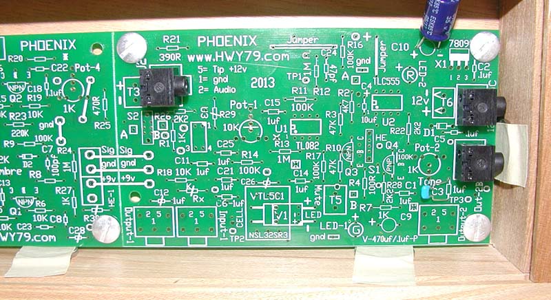
The board is placed in the wood box with
nickels in place to match the template for positioning and gluing.
The holes are not yet drilled in this photo
Stand-off stud & screws are staggered at the board score.
The three required Jacks are shown, Mount with extra lead length (1/2")
for C10 to move it outside for clearance of the J2 cable and extra for C3
to be used as a test connection. Nickels are used with masking tape so the
board position is accurate for gluing the mounting studs. Firmly (not
tight) attach
the five screw/studs to the PCB before gluing into position. Apply epoxy around
the stud edges for adhesion to the wood base while avoiding
the screw threads.
It is
important the aluminum screw is first threaded into a #8 steel nut and the
aluminum studs have a #8 steel screw threaded through them. This is to clean contamination off the threads, the aluminum pieces together
slightly dirty can seize together! Test each combo before securing them to
the board. Finger tighten firm.
Dana's Notes:
(SewerPipe) By following these
steps the position of the PCB placed in the box can be “Shifted” a slight amount,
the Plugged in cables help “Align” the PCB in the best position
for off centered holes. 1. Mount stand-offs
(screw/studs) to the printed circuit board, finger firm but "not" tight (no epoxy yet) 2. Place PCB in
the box and study the position and fit. (no epoxy yet) 3.
Plug the cables into the Jacks through the drilled out holes B C (F if used) in the wood box. 4.
Proceed if you have
proper clearance, otherwise you may need to elongate one of the holes for a better
fit.
5. Unplug the cables from the Jacks and lift out the PCB and apply the epoxy around the bottom
edges of the stand-off studs with a Q-Tip, avoid
the threads. 6.
Place the pc board back in its proper position, plug in the cables at B C (F if used)
and position the board. 7.
Carefully weight down the PCB and let the epoxy cure overnight.
Using jacks/plugs can help position the PCB in its final location for
gluing if your
holes did not have precision alignment.
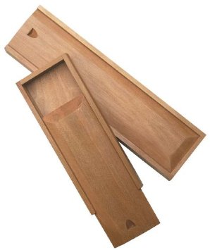
From Amazon
Purchase two of the shorter boxes shown beneath the longer one - $11 ea.  This
needs study, if
the longer box is
used it leaves a space for a pitch
preview amp or
something? (-' To use the same drill hole template unmodified
the add-on accessory could occupy the top portion of the enclosure box
away from the L2 antenna side. This
needs study, if
the longer box is
used it leaves a space for a pitch
preview amp or
something? (-' To use the same drill hole template unmodified
the add-on accessory could occupy the top portion of the enclosure box
away from the L2 antenna side.
Template needs +
for a Mute Switch location, needs some
study.
(-'
Possibly two
holes by the Vactrol, one for the green LED-1 which also indicates Muted
when off and switch up Un-Mutes. Needs study. The
same two holes on Pitch board one could be for the red LED-2 which allows
proper Null point distance setting when Volume is Muted. The second hole
for ?
Using the side mounting
allows the back side of the enclosure to face the audience as an ideal surface to mount a wood carving or something
artistic.
<=Main
Page
|