|
My using
PWM for volume control opens the door to many other possibilities of
control.
I think using
a preAmp/equalizer is good to balance out the audio level of the playing
range. The PreAmp extra stereo channel can be used as the ear
bud pre-amp while
using an inline volume control on the bud.
Schematic
Corrections:
Phoenix
Schematic PDF
Drawn by Don
Parrish-Bell
9.19.13
R7-?
The board indicates 1K, I have found 470 is better for near the
loop silence. If you like your volume response don't change it.
C19-?
on volume should be 100pf as C17 is also 100pf.
C10-470uf is on wrong side of
power diode. ?
C24-47pf ?
missing, R29 2K2 ?
missing
Output-2b & Out-2b share
the same connections unless custom modified to use Out-2b for another
purpose. ?
The wiper on Pot-2 should
have a direct connection to the P side of the transformer. ?
Don,
front panel
line level adjust with 1/4 jack and using the amber LED with the switched
ground for mute indication is a nice touch. Maybe indicate
switch as DPDT?
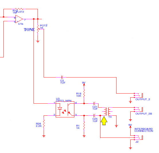
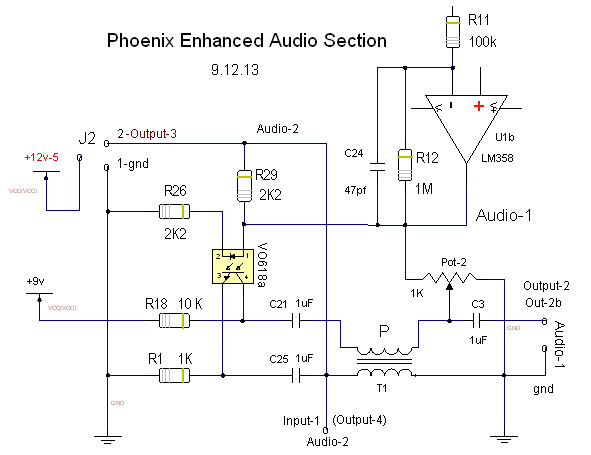
This
section above is drawn incorrect, see corrected below
Mods
& Wires Explained Here
Ideas: When
it comes to sound very small changes to the wave shape can have a big
effect to what you hear. Pot-2
This effect is very subtle and may not be
noticed unless Pot-1 is delivering enough signal through U1b
to drive the Opto. R29-2k2
might be a good spot for a 5K linear Pot to blend/balance J2 output
with Audio-1 & Audio-2, the current value is the best. Increasing the
value of R29 will decrease the output amplitude
slightly but the best sound is what
we are after. R29
is a low impedance spot so a twisted wire pair should work fine. The
Opto modulating trick came about from my
first years of experiments, beside the phase shift I noticed that audio on
a LED talking to a photo-transistor properly balanced created a more
interesting sound.
. Notes
of Interest: LED-1
Green, this moves the Vactrol circuit cutoff voltage 2.1v higher for
better quieting response. Any higher volume will not completely cut off. R32
at green LED-1 spreads out the quiet shading near the loop. To try
this is best if R32 is switched in or out. This will not work with
a poorly responding volume setup. Fixed
RF oscillator R27-1k creates better thermal drift balance, C8 keeps
cold side of coil at RF ground. This R27 could be jumped to compare if
having it is any real effect. The best
ground loop
filter I found to place between the theremin and amplifier is the
Absolute PNF 200 but it still attenuates the low end
(<100 hz) slightly which encourages the use of a pre-amp/equalizer to
bring the low end level back up. Audio-1
is standard
sound Audio-2 harmonically enhanced sound
using T1 & V0618a. Mount
-> R29
& C25 with longer
leads (near U3)
so one side can be clipped to experiment if its effect in or out of
circuit is better. The sound will quiet without these but it may give a
more harmonically rich effect? The audio signal from the 3 x 3
oscillator board must be driving the OpAmp U1 strong enough to make
the magic happen. Ideal is audio greater than 2v p-p at U3 pin 1.
|